
Installation guide

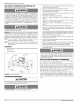

25" x 16"
FILTER
GRILLE
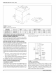
FIGURE 3: Platform Installation
HORIZONTAL MODELS
Horizontal Installations With a Cooling Coil Cabinet
The furnace should be installed with coil cabinet part number specifi-
cally intended for Horizontal application. If a matching cooling coil is
used, it may be placed directly on the furnace outlet and sealed to pre-
vent leakage. Fellow the ceiI instructions for installing the supply ple-
num. For details of the coiI cabinet dimensions and installation
requirements, refer to the installation instructions supplied with the coil
cabinet
The perforations in the wrapper flanges must be bent away from the
heat exchanger to create duct flanges so the air conditioning ceil can be
properly seated on the furnace.
Attach the supply plenum to the air conditioning coiI cabinet outlet duct
flanges through the use of S cleat material when a metal plenum is
used. The use of an approved flexible duct connector is recommended
on all installations. The connection to the furnace, air conditioning coil
cabinet and the supply plenum should be sealed to prevent air leakage.
The sheet metal should be crosshatched to eliminate any popping of
the sheet metal when the indoor fan is energized.
The minimum plenum height is 12" (30.5 cm). If the plenum is shorter
than 12" (30.5 cm) the turbulent air flow may cause the limit controls not
to operate as designed, or the limit controls may not operate at all. Also
the plastic drain pan in the air conditioning coil can overheat and melt.
Refer to the installation instructions supplied with the air conditioning
coil for additional information.
Horizontal Installations Without a Cooling Coil Cabinet
When installing this appliance, the furnace must be installed so as to
create a closed duct system, the supply duct system must be con-
nected to the furnace outlet and the supply duct system must terminate
outside the space containing the furnace. When replacing an existing
furnace, if the existing plenum is not the same size as the new furnace
then the existing plenum must be removed and a new plenum installed
that is the proper size for the new furnace.
Attach the supply plenum to the furnace outlet duct flanges through the
use of S cleat material when a metal plenum is used. The use of an
approved flexible duct connector is recommended on all installations.
This connection should be sealed to prevent air leakage. The sheet
metal should be crosshatched to eliminate any popping of the sheet
metal when the indoor fan is energized. On all installations without a
66840/035-20003-001 Rev. B (1205)
coil, a removable access panel is recommended in the outlet duct such
that smoke or reflected light would be observable inside the casing to
indicate the presence of leaks in the heat exchanger. This access cover
shall be attached in such a manner as to prevent leaks.
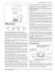
Mobile Home and Modular Home Upflow/Horizontal Return
Plenum Connections
The return air duct and the return air plenum is required by the furnace
manufacturer.
If a upflow return air duct system and return plenum are required by
state, local, or regional codes then the return plenum may be connected
to the furnace inlet and must terminate outside the space containing the
furnace. The external air filter accessory shown in Figure 7 is designed
and recommended for use inside the return plenum.
Attach the return plenum to the furnace inlet duct flanges. This is typi-
cally through the use of S cleat material when a metal plenum is used
for installations where a return air duct system is utilized, the use of a
listed flexible duct connector is recommended. The connection of the
plenum to the furnace and all the ducts connecting to the plenum must
be sealed to prevent air leakage. The sheet metal should be cross-
hatched to eliminate any popping of the sheet metal when the indoor
fan is energized.
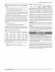
The duct system is a very important part of the installation. If the duct
system is improperly sized the furnace will not operate properly. The
ducts attached to the furnace must be of sufficient size so that the fur-
nace operates at the specified external static pressure and within the air
temperature rise specified on the nameplate and in Table 8.
An upflow return air duct and plenum can be attached to the bottom,
side, both sides, or bottom and side of the furnace as shown in Figure
4.
Attic and crawl space installations must meet all minimum clearances to
combustibles and have floor support with required service accessibility
Refer to Figures 4 and 5. All attic and crawl space installations must
have a return air duct system and return plenum. Horizontal installa-
tions require a single return duct as shown in Figure 4. A side return is
not required in a horizontal application.
IMPORTANT: When replacing an existing furnace, if a return air plenum
is used and the existing plenum is not the same size as the new furnace
then the existing plenum must be removed and a new plenum installed
that is the proper size for the new furnace. If a return duct mounted filter
rack or filter grille is being used see the instructions provided with that
accessory for proper hole cut size.
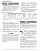
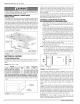
ATTIC INSTALLATION
LINE CONNECT ONLY PERMISSIBLE BETWEEN
LINES FORMED BY THE INTERSECTION OF
FURNACE TOP AND TWO SIDES AND BUILDING
JOISTS, STUDS, OR FRAMING
FILTER RACK MUST
BE A MI NIMUM DISTANCE
OF 18" (45.7 CM) F!
THE FURNACE
SUPPLY
AIR
TRAP
PLYWOOD
FLOOR
SHEET METAL IN FRONT OF FURNACE COMBUSTION
AIR OPENINGS IS RECOMMENDED
FIGURE 4: Typical Attic Installation
This appliance is design certified for line contact when the furnace is
installed in the horizontal left or right position. The line contact is only
permissible between lines that are formed by the intersection of the top
and two sides of the furnace and the building joists, studs or framing.
This line may be in contact with combustible material.
Unitary Products Group 7