
Installation guide
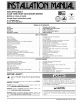


66840/035-20003-001Rev.B(1205)
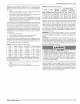
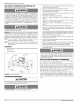
13-15/16
(85A cm)
(58A cm)
29-3/4
,7 cm) (75,6 cm_.
31-1/2
(80.0 cm)
FIGURE 1: Dimensions
TABLE 4: Cabinet and Duct Dimensions
BTUH (kW) Cabinet Cabinet Dimension
Input/Output CFM (m3/min) Size A(in.) A(cm) B(in.)* B(cm)*
/b/6U (22.0/1/.6) 1200 (33.98) B 1/ 1/2 44.b 16 1/2 41.9
/bt6U (22.0/1/.6) !600 (46.31) C 21 53.3 20 50.8
100/80 (29.3/23A) 1600 (45.31) C 21 53.3 20 50.8
* Dimensions "B", "C', "D', and "E" arewith duct flanges turned up "F', "G","H", and "J" are with flanges flat
MOBILE HOME AND MODULAR HOME UPFLOW
RETURN PLENUM CONNECTION
Return air may enter the furnace through the side(s) or bottom depend-
ing on the type of application. Return air may not be connected into the
rear panel of the unit. For single return application, see data and notes
on blower performance data tables in this manual.
BOTTOM RETURN AND ATTIC INSTALLATIONS
Bottom return applications normally pull return air through a base plat-
form or return air plenum. Be sure the return platform structure or return
air plenum is suitable to support the weight of the furnace.
The return air ducts to the furnace must have a total cross sectional
area of not less than two square inches per 1000 BTU H of furnace input
rating for heating operation. If air conditioning is to be installed with the
furnace, larger return air ducts may be required, depending on the
capacity of the air conditioner and the airflow required. The return air
opening in the top of the furnace is large enough for the largest capacity
air conditioner for which the furnace blower is rated. The return air duct
or plenum can be connected to the furnace by performing the following
steps:
1. Bend the 3/4" (1.905 cm) flanges that will be used to attach the
return air plenum using the scribe marks in the furnace base.
Refer to Figure 1 for flange locations.
2. Be sure to seal the furnace to plenum connections to prevent air
leakage. Refer to Figure 1 for unit and plenum dimensions.
Attic installations must meet all minimum clearances to combustibles
and have floor support with required service accessibility.
INSTALLATION RECOMMENDATIONS
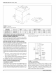
FLOOR INSTALLATIONS
As shown below in Figure 2, the furnace may be installed directly on the
floor of the home, using a side return air connection. A short duct
should be connected to the side cutout in the furnace casing. The other
end of the return air duct should be connected to a minimum 25" x 16"
filter grille. If a Blend Air ventilation system is to be installed, the return
C(in.)* C(cm)*
20 3/8 t1.8
20 3/8 51 .U
20 3/8 51.8
air duct must be long enough so that the Blend Air damper can be
mounted in the top of the duct.
PLENOM
1 I I J ( fZZCOIL
[ [l rd CAO'NET
F--_ ( /. H_ BLENDAIR
_I_ FLEX DUCT
_I I # [_ BLEND AIR
/DAMPER
I _[ 25"x 18"
I H _ FILTER
_-GRILLrT=._ E
FIGURE 2: Floor Installation
PLATFORM INSTALLATIONS
As shown below in Figure 3, the furnace may be installed on a raised
platform. The platform must be a minimum of 20" in height and a filter
grille with a minimum area of 25" x 16" must be mounted in the front,
back or side of the platform. If a Blend Air ventilation system is to be
installed, the platform must be wide enough so that the Blend Air
damper can be mounted in the top of the platform
6 Unitary Products Group