
Installation guide


Example:Thefurnaceinputis80,000BTUH,1,200CFM.Therecom-
mendedductareais280sq.in,therearetwo8x14rectangularducts
attachedtotheplenumandtherearetwo7inchroundductsattachedto
thefurnace.
1. Take8x14,whichequals112sq.in.X2,whichequals224square
inchthengotoroundductsizelocatedinTable2.
2. Thesquareinchareafor7inchroundpipeis38.4,multiplyby2for
tworoundductswhichequals76.8squareinch.
3. Thentakethe224squareinchfromtherectangularductandaddit
tothe76.8sq.in,ofroundduct.Thetotalsquareinchofduct
attachedtothefurnaceplenumis300.8squareinch.Thisexceeds
therecommended280squareinchofduct.
Inthisexample,theductsystemattachedtotheplenumhasasufficient
areasothatthefurnaceoperatesatthespecifiedexternalstaticpres-
sureandwithintheairtemperaturerisespecifiedonthenameplate.
Considerationshouldbegiventotheheatingcapacityrequiredandalso
totheairquantity(CFM)required.Thesefactorscanbedeterminedby
calculatingtheheatlossandheatgainofthehomeorstructure.Ifthese
calculationsarenotperformedandthefurnaceisover-sized,thefollow-
ingmayresult:
1. Shortcyclingofthefurnace.
2. Widetemperaturefluctuationsfromthethermostatsetting.
3. Reducedoveralloperatingefficiencyofthefurnace.
Thesupplyandreturnductsystemmustbeof adequatesizeand
designedsuchthatthefurnacewilloperatewithinthedesignedairtem-
peratureriserangeandnotexceedthemaximumdesignedstaticpres-
sure.Thesevaluesarelistedinthetablebelow.
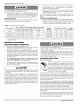
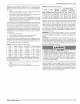
TABLE2:MinimumDuctSizingForProperAirflow
Input
BTU/H
(kW)
75000
(2198)
75000
(2198)
100000
(2931)
Airflow Return I Rectangular 2 Round 2 Supply 3
CFM In s in. x in in In s
(m 3) (cm _) (cm x cm) (cm) dia. (cm _)
1,200 280 14 x 20 18 216
(3398) (711) (356 x 508) (457) (549)
1,600 360 18 x 20 22 280
(4531) (914) (457 x 508)) (558) (711)
1,600 360 18 x 20 22 280
(4531) (914) (45.7 x 50.8) (558) (711)
NOTE: This chart does not replace proper duct sizing calculations or take into
account static pressure drop for run length and fittings. Watch out for the temper-
ature rise and static pressures.
1 Maximum return air velocity in rigid duct @ 700 feet per minute (19.82 m 3/
minute)
2 Example return main trunk duct minimum dimensions
3 Maximum supply air velocity in rigid duct @ 900 feet per minute (25.49 m 3 /
minute)
66840/035-20003-001 Rev. B (1205)
TABLE 3: External Static Pressure Range
Input Output
MBH kW MBH kW
75 22.0 60 17.6
75 22.0 60 17.6
100 29.3 80- 23.4
Nominal
Air Flow
CFM cmm
1200 34.0
1600 45.3
1600 45.3
Ext. Static Pressure
Minimum Maximum
In.W.C kPa In.W.C kPa
0.12 0.0299 0.50 0.!245
0.12 0.0299 0.50 0.1245
0.15 0.0374 0.50 0.!245
TABLES 2 and 3 are to be used as a guide only to help the installer
determine if the duct sizes are large enough to obtain the proper air flow
(CFM) through the furnace. TABLES 2 and 3 ARE NOT to be used to
design ductwork for the building where the furnace is being installed.
There are several variables associated with proper duct sizing that are
not included in the tables. To properly design the ductwork for the build-
ing, Refer to the ASHRAE Fundamentals Handbook, Chapter on
"DUCT DESIGN" or a company that specializes in Residential and Mod-
ular Home duct designs.
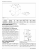
IMPORTANT: The minimum plenum height is 12" (30.5). The furnace
will not operate properly on a shorter plenum height. The minimum rec-
ommended rectangular duct height is 4 inches (10 cm) attached to the
plenum.
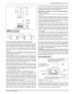
IMPORTANT: The air temperature rise should be taken only after the
furnace has been operating for at least 15 minutes. Temperatures and
external static pressures should be taken 6" (15 cm) past the first bend
from the furnace in the supply duct and the return duct. If an external fil-
ter box or an electronic air cleaner is installed, take the return air read-
ings before the filter box or air cleaner.
The supply air temperature MUST NEVER exceed the Maximum
Supply Air Temperature, specified on the nameplate.
Operating the furnace above the maximum supply air temperature
will cause the heat exchanger to overheat, causing premature heat
exchanger failure. Improper duct sizing, dirty air filters, incorrect
manifold pressure, incorrect gas orifice and/or a faulty limit switch
can cause the furnace to operate above the maximum supply air
temperature. Refer to sections II, III and IX for additional informa-
tion on correcting the problem.
If a matching cooling coil is used, it may be place directly on the furnace
outlet and sealed to prevent leakage. Follow the coil instructions for
installing the supply plenum. On all installations without a coil, a remov-
able access panel is recommended in the outlet duct such that smoke
or reflected light would be observable inside the casing to indicate the
presence of leaks in the heat exchanger. This access cover shall be
attached in such a manner as to prevent leaks.
Unitary Products Group 5