
Installation guide


66840/035-20003-001Rev.B(1205)
Improper installation in an ambient below 32°t: (0.0 ° C) could create
a hazard, resulting in damage, injury or death.
3. If this furnace is installed in an unconditioned space and an
extended power failure occurs, there will be potential damage to
the internal components. Following a power failure situation, do
not operate the unit until inspection and repairs are performed.
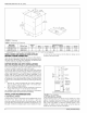
Clearances for access:
Ample clearances should be provided to permit easy access to the unit.
The following minimum clearances are recommended:
1. Twenty-four (24) inches (61 cm) between the front d the furnace
and an adjacent wall or another appliance, when access is
required for servicing and cleaning.
2. Eighteen (18) inches (46 cm) at the side where access is required
for passage to the front when servicing or for inspection or replace-
ment of flue/vent connections.
In all cases, accessibility clearances shall take precedence over clear-
ances for combustible materials where accessibility clearances are
greater.
Installation in a residential aaraoe:
3. A gas-fired furnace for installation in a residential garage must be
installed so the burner(s) and the ignition source are located not
less than 18 inches (46 cm) above the floor, and the furnace must
be located or protected to avoid physical damage by vehicles.
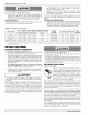
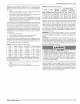
TABLE 1: Unit Clearances to Combustibles
TOP FRONT REAR SIDES SINGLE WALL VENT
APPLICATION
In. (cm) In, (cm) In. (cm) In. (cm) In. (cm)
UPFLOW 1 (254) 2 (5.08) 0 (0.0) 0 (00) 6 (1524)
UPFLOW B-VENT 1 (254) 1 (2.54) 0 (0.0) 0 (00) N/A
HORIZONTAL 1 (254) 2 (5.08) 0 (0.0) 1 (5.08) 6 (1524)
HORIZONTAL B-VENT 1 (2.54)) 1 (254) 0 (0.0) 0 (00) N/A
FLOOR/ LINE
CLOSET ALCOVE ATTIC
BOTTOM CONTACT
COMBUSTIBLE YES YES YES NO
COMBUSTIBLE YES YES YES NO
COMBUSTIBLE NO YES YES YES 1
COMBUSTIBLE NO YES YES YES 1
1. Line contact only permitted between lines formed by the intersection of the rear paneI and side paneI (top in horizontal position) of the furnace jacket and buitding
joists, studs or framing
SECTION Ih DUCTWORK
DUCTWORK GENERAL INFORMATION
The duct system's design and installation must:
1. Handle an air volume appropriate for the served space and within
the operating parameters of the furnace specifications.
2. Be installed in accordance with standards of NFPA (National Fire
Protection Association) as outlined in NFPA pamphlets 90A and
90B (latest editions) or applicable national, provincial, or state, and
local fire and safety codes. In Canada refer to the National Gas
and Propane Installation Code B149.!-00, Provincial, Local Fire
and Safety Codes.
3. For manufactured (mobile) home and modular home return
duct system installation: The return air duct and the return air
plenum are required by the furnace manufacturer.
4. Complete a path for heated or cooled air to circulate through the
air conditioning and heating equipment. Air must circulate to and
from the conditioned space.
A CAUTION
The cooling coil must be installed in the supply air duct, down-
stream of the furnace. Cooled air may not be passed over the heat
exchanger.
When the furnace is used in conjunction with a cooling coil, the coil
must be installed parallel with, or in the supply air side of the furnace to
avoid condensation in the primary heat exchanger. When a parallel flow
arrangement is used, dampers or other means used to control airflow
must be adequate to prevent chilled air from entering the furnace. If
manually operated, the damper must be equipped with means to pre-
vent the furnace or the air conditioner from operating unless the damper
is in full heat or cool position.
kWARNING
The duct system must be properly sized to obtain the correct airflow
for the furnace size that is being installed.
Refer to Table 8 and the furnace rating plate for the correct rise
range and static pressures
If the ducts are undersized, the result will be high duct static pres-
sures and/or high temperature rises which can result in a heat
exchanger OVERHEATING CONDITION. This condition can result
in premature heat exchanger failure, which can result in personal
injury, property damage, or death.
DUCTWORK INSTALLATION
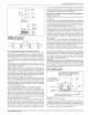
Upflow Instructions
Attach the supply plenum to the furnace outlet duct
connection flanges. This is typically through the use of
S cleat material when a metal plenum is used. The use
of an approved flexible duct connector is recom-
mended on all installations. This connection should be
sealed to prevent air leakage. The sheet metal should
be crosshatched to eliminate any popping of the sheet
metal when the indoor fan is energized.
When replacing an existing furnace, if the existing plenum is not the
same size as the new furnace then the existing plenum must be
removed and a new plenum installed that is the proper size for the new
furnace. If the plenum is shorter than 12" (30.5 cm) the turbulent air flow
may cause the limit controls not to operate as designed, or the limit con-
trois may not operate at all.
The duct system is a very important part of the installation. If the duct
system is improperly sized the furnace will not operate properly.
The ducts attached to the furnace plenum, should be of sufficient size
so that the furnace operates at the specified external static pressure
and within the air temperature rise specified on the nameplate.
Table 2 is a guide for determining whether the rectangular duct system
that the furnace is being connected to be of sufficient size for proper fur-
nace operation.
Use the Example below to help you in calculating the duct area to deter-
mine whether the ducts have sufficient area so that the furnace oper-
ates at the specified external static pressure and within the air
temperature rise specified on the nameplate.
4 Unitary Products Group