
Installation guide


66840/035-20003-001Rev.B(1205)
Thetemperaturerise,ortemperaturedifferencebetweenthereturnair
andtheheatedsupplyairfromthefurnace,mustbewithintherange
shownonthefurnaceratingplateandwithintheapplicationlimitations
asshowninTable8.
Afterabout15minutesofoperation,determinethefurnacetemperature
rise.Takereadingsofboththereturnairandtheheatedairintheducts,
aboutsixfeet(1.83m)fromthefurnacewheretheywillnotbeaffected
byradiantheat.Increasetheblowerspeedtodecreasethetemperature
rise;decreasetheblowerspeedtoincreasetherise.
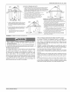
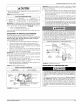
Alldirect-driveblowershavemulti-speedmotors.Theblowermotor
speedtapsarelocatedinthecontrolboxintheblowercompartment.
Referto Figure33,andtheunitwiringlabeltochangetheblower
speed.Tousethesamespeedtapforheatingandcooling,theheatter-
minalandcoolterminalmustbeconnectedusingajumperwireand
connectedtothedesiredmotorlead.Placeallunusedmotorleadson
Parkterminals.Twoareprovided.
CAUTION1
Do not energize more than one motor speed at a time or damage to
the motor wil! result.
ADJUSTMENT OF FAN CONTROL SETTINGS
This furnace is equipped with a time-on/time-off heating fan control. The
fan on delay is fixed at 30 seconds. The fan off delay has 4 settings (60,
90, 120 and !80 seconds). The fan off delay is factory set to 120 sec-
onds. The fan-off setting must be long enough to adequately cool the
furnace, but not so long that cold air is blown into the heated space. The
fan-off timing may be adjusted by positioning the jumper on two of the
four pins as shown in Figure 33.
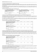
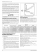
TABLE 16: Filter Performance - Pressure Drop Inches W.C. and (kPa)
60
180
FIGURE 33: Typical Heat!Cool Speed Tap Connections
FILTER PERFORMANCE
The airflow capacity data published in Table 17 represents blower per-
formance WITHOUT filters. To determine the approximate blower per-
formance of the system, apply the filter drop value for the filter being
used or select an appropriate value from the Table 16.
The filter pressure drop values in Table 16 are typical values for the
type of filter listed and should only be used as a guideline. Actual pres-
sure drop ratings for each filter type vary between filter manufacturers.
Minimum Opening Size Filter Type
Airflow Range Disposable Hogs Hair* Pleated
1 Opening 2 Openings 1 Opening 2 Openings 1 Opening 2 Openings 1 Opening 2 Openings
CFM Cm/m In3 m3 In3 I m3 inwc kPa inwc kPa inwc kPa inwc kPa inwc kPa
I
0-750 0-21.24 230 0.0038 !li!_ 0.01 0.0025 i_lil_ 0.01 0.0025 i_Ii1_i_015 0.0374
751 - 1000 21.27- 28.32 330 0.0054 0.05 0.0125 0.05 0.0125 0.2 0.0498
1001 - 1250 28.35- 35.40 330 0.0054 0.1 0.0249 0.1 0.0249 0.2 0.0498
1251 - 1500 35.42- 42.47 330 0.0054 0.1 0.0249 0.1 0.0249 0.25 0.0623
1501 - 1750 42.50- 49.55 380 0.0062 ............ 0.15 0.0374 0.14 0.0349 0.3 0.0747
1751-2000 49.58-56.63 380 0.0062 658 0.0108 0.19 0.0473 0.!1 0.0274 0.18 0.0448 0.! 0.0249 0.3 0.0747 0.!7 0.0423
2001 &Above 56.66&Above 463 0.0076 658 0.0108 0.!9 0.0473 0.11 0.0274 0.18 0.0448 0.1 0.0249 0.3 0.0747 0.17 0.0423
* Hogs Hair Filtersare the type supptied with furnace (if suppIied)
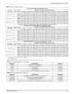
APPLYING FILTER PRESSURE DROP TO
DETERMINE SYSTEM AIRFLOW
To determine the approximate airflow of the unit with a filter in place, foI-
low the steps below:
1. Select the filter type.
2. Select the number of return air openings or calculate the return
opening size in square inches to determine the proper filter pres-
sure drop.
3. Determine the External System Static Pressure (ESP) without the
filter.
4. Select a filter pressure drop from the table based upon the number
of return air openings or return air opening size and add to the
ESP from Step 3 to determine the total system static.
5. If total system static matches a ESP value in the airflow table (i.e.
0.20 w.c. (50 Pa), 0.60 w.c. (150 Pa), etc.,) the system airflow cor-
responds to the intersection of the ESP column and Model/Blower
Speed row.
6. If the total system static falls between ESP values in the table (i.e.
0.58 w.c. (144 Pa), 0.75 w.c. (187 Pa), etc.), the static pressure
may be rounded to the nearest value in the table determining the
airflow using Step 5 or calculate the airflow by using the following
example.
Example: For a 75,000 BTUH (21.98 kW) furnace with 2 return open-
ings and operating on high-speed blower, it is found that total system
static is 0.38" w.c. To determine the system airflow, complete the follow-
ing steps:
Obtain the airflow values at 0.30 w.c. (75 Pa) & 0.40 w.c. (99.6 Pa) ESR
Airflow @ 0.30": 1408 CFM (39.8 m3/min)
Airflow @ 0.40": 1343 CFM (38.0 m3/min)
Subtract the airflow @ 0.30 w.c. (75 Pa) from the airflow @ 0.40 w.c.
(99.6 Pa) to obtain airflow difference.
1343 - 1408 = -65 CFM (!.89 m3/min)
Subtract the total system static from 0.30 w.c. (75 Pa) and divide this
difference by the difference in ESP values in the table, 0.40 w.c.
(99.6 Pa) - 0.30 w.c. (75 Pa), to obtain a percentage.
(0.38- O.30) / (O.40- 0.3O) = O.8
Multiply percentage by airflow difference to obtain airflow reduction.
(O.8) X (-65) = -52
Subtract airflow reduction value to airflow @ 0.30 w.c. (75 Pa) to obtain
actual airflow @ 0.38 in wc (94.6 Pa) ESP.
1408 - 52 = 1356
24 Unitary Products Group