
Installation guide


[A CAUTION]
Be sure to relight any gas appliances that were turned off at the
start of this input check.
TABLE 14: Inlet Gas Pressure Range
INLET GAS PRESSURE RANGE
Natural Gas Propane (LP)
Minimum 45" WC (1 12 kPa) 80 _W.C (1 99 kPa)
Maximum 105 _W.C (261 kPa) 130" (3.24 kPa) W.C.
IMPORTANT: The inlet gas pressure operating range table specifies
what the minimum and maximum gas line pressures must be for the fur-
nace to operate safely. The gas line pressure MUST BE a minimum of
• 7" W.C. (1.74 kPA) for Natural Gas
• !1" W.C. (2.74 kPA) for Propane (LP) Gas
in order to obtain the BTU input specified on the rating plate and in
these instructions.
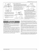
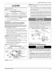
ADJUSTMENT OF MANIFOLD GAS PRESSURE
Manifold gas pressure may be measured at the gas valve.
Turn gas off at the ball valve or gas cock on gas supply line
before the gas valve. Find the pressure ports on the gas
valve marked OUT P and IN P.
1. The manifold pressure must be taken at the port marked OUT P.
2. The gas line pressure must be taken at the port marked IN P.
3. Using a 3/32" Allen wrench, loosen the setscrew by turning it 1
turn counter clockwise. DO NOT REMOVE THE SET SCREW
FROM THE PRESSURE PORT.
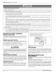
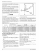
4. Use the 4" (10.2 cm) piece of 1/8" (0.3 cm) tubing to connect the
positive side of the manometer to the gas valve manifold pressure
port. Refer to Figure 32 for connection details.
IMPORTANT: The cap for the pressure regulator must be removed
entirely to gain access to the adjustment screw. Loosening or tightening
the cap does not adjust the flow of gas.
5. Refer to Figure 31 for location of pressure regulator adjustment
cap and adjustment screw on main gas valve.
6. Turn gas and electrical supplies on and follow the operating
instructions to place the unit back in operation.
7. Adjust manifold pressure by adjusting gas valve regulator screw
for the appropriate gas per the following:
TABLE 15: Nominal Manifold Pressure
NOMINAL MANIFOLD PRESSURE
Natural Gas 3.5" w.c. (0.87 kPa)
Propane (LP) Gas 10.0" wc (2488 kPa)
OUTLET
PRESSURE r_ _ Im
PORT _ I I
WRENCH J __
BOSS INLET_ _
PRESSURE
PORT
ENT PORT
OUTLET
N REGULATOR
STMENT
ON/OFF SWITCH
(Shown in OFF position)
FIGURE 31: Gas Valve
66840/035-20003-001 Rev. B (1205)
IMPORTANT: If gas valve regulator is turned in (clockwise), manifold
pressure is increased. If screw is turned out (counterclockwise), mani-
fold pressure will decrease.
8. After the manifold pressure has been adjusted, re-calculate the
furnace input to make sure you have not exceeded the specified
input on the rating plate. Refer to "CALCULATING THE FURNACE
INPUT (NATURAL GAS)".
9. Once the correct BTU (kW) input has been established, turn the
gas valve to OFF and turn the electrical supply switch to OFF; then
remove the flexible tubing and fittings from the gas valve pressure
tap and tighten the pressure tap plug using the 3/32" Allen wrench.
10. Turn the electrical and gas supplies back on, and with the burners
in operation, check for gas leakage around the gas valve pressure
port for leakage using an approved gas detector, a non-corrosive
leak detection fluid, or other leak detection methods.
AWARNING
The manifold pressure must be checked with the screw-off cap for
the gas valve pressure regulator in place. If not, the manifold pres-
sure setting could result in an over-fire condition. A high manifold
pressure wil! cause an over-fire condition, which could cause pre-
mature heat exchanger failure. If the manifold pressure is too low,
sooting and eventual clogging of the heat exchanger could occur.
Be sure that gas valve regulator cap is in place and burner box to
gas valve pressure reference hose is connected.
MAINFOLD PRESSURE "U" TUBE CONNECTION
OUTLET
_j_llr_F_ / PRESSURE TAP
GAS VALVE7 -_ MANIFOLDPIPE
_. / 1/4"TUBING
\ I_j,c._c _ WATER
FLAME U-TUBE I I_--_: COLUMN
SENSOR MANOMETER II_--_: GAS
I_-- _-- PRESSURE
SHOWN
FIGURE 32: Reading Gas Pressure
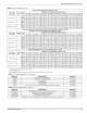
ADJUSTMENT OF TEMPERATURE RISE
ADANGER
The temperature rise, or temperature difference between the return
air and the supply (heated) air from the furnace, must be within the
range shown on the fumace rating plate and within the application
limitations shown in Table 8 "ELECTRICAL AND PERFORMANCE
DATA".
The supply air temperature cannot exceed the "Maximum Supply
Air Temperature" specified in these instructions and on the fur-
nace rating plate. Under NO circumstances can the furnace be
allowed to operate above the Maximum Supply Air Temperature.
Operating the furnace above the Maximum Supply Air Temperature
wil! cause premature heat exchanger failure, high levels of Carbon
Monoxide, a fire hazard, personal inju04 property damage, and/or
death.
Unitary Products Group 23