
Installation guide


66840/035-20003-001Rev.B(1205)
HORIZONTAL VENT APPLICATIONS AND
TERMINATION
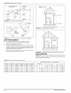
When selecting the location for a horizontal combustion air / vent termi-
nation, the following should be considered:
1. Observe all clearances listed in vent clearances in these instruc-
tions.
2. Termination should be positioned where flue products will not dam-
age plants or shrubs or air conditioning equipment.
3. Termination should be located where it will not be affected by wind
gusts, light snow, airborne leaves or allow recirculation of flue
gases.
4. Termination should be located where it will not be damaged or
exposed to flying stones, balls, etc.
5. Termination should be positioned where vent vapors are not objec-
tionable.
6. Horizontal portions of the vent system must slope upwards and be
supported to prevent sagging. The vent system may be supported
by the use of clamps or hangers secured to a permanent part of
the structure every 4 ft. (1.22 m).
FAN-ASSISTED COMBUSTION SYSTEM
An appliance equipped with an integral mechanical means to either
draw or force products of combustion through the combustion chamber
and/or heat exchanger.
Ambient Combustion Air Supply
This type installation will draw the air required for combustion from
within the space surrounding the appliance and from areas or rooms
adjacent to the space surrounding the appliance. This may be from
within the space in a non-confined location or it may be brought into the
furnace area from outdoors through permanent openings or ducts. A
single, properly sized pipe from the furnace vent connector to the out-
doors must be provided. For upflow models combustion air is brought
into the furnace through the unit top panel opening.
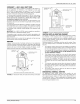
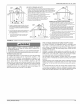
VENT PiPE CEMENTS
-- INTO SOCKET JUST
ABOVE TOP PANEL
COMBUSTION
FIGURE 28: Combustion Airflow Path Through The Furnace Casing to
the Burner Box
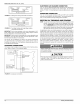
AWARNING
This type of installation requires that the supply air to the appli-
ance(s) be of a sufficient amount to support all of the appliance(s)
in the area. Operation of a mechanical exhaust, such as an exhaust
fan, kitchen ventilation system, clothes dryer or fireplace may cre-
ate conditions requiring special attention to avoid unsatisfactory
operation of gas appliances. A venting problem or a lack of supply
air will result in a hazardous condition, which can cause the appli-
ance to soot and generate dangerous levels of CARBON MONOX-
IDE, which can lead to serious injury, property damage and / or
death.
An unconfined space is not Iess than 50 cu.ft (1.42 m3) per 1,000 Btu/
hr (0.2928 kW) input rating for all of the appliances installed in that
area.
Rooms communicating directly with the space containing the appli-
ances are considered part of the unconfined space, if openings are fur-
nished with doors.
A confined space is an area with less than 50 cu.ft (1.42 m 3) per 1,000
Btu/hr (0.2928 kW) input rating for alI of the appliances installed in that
area. The following must be considered to obtain proper air for combus-
tion and ventilation in confined spaces.
Combustion Air Source From Outdoors
The blocking effects of louvers, grilles and screens must be given con-
sideration in calculating free area. If the free area of a specific louver or
grille is not known, refer to Table 11, to estimate free area.
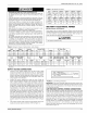
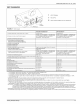
TABLE 11: Estimated Free Area
Wood or MetaI Wood 20-25%*
Louversor Grilles Metal 60-70% *
1/4" (0.635 cm)
Screens+
mesh or larger 100%
Do not useIess than 1/4" (0635 cm) mesh
+ Free area or Iouvers and gritle varies widely; the installer should follow Iou-
ver or grilte
manufacturer's instructions.
Dampers, Louvers and Grilles (Canada Only)
1. The free area of a supply air opening shall be calculated by sub-
tracting the blockage area of all fixed louvers grilles or screens
from the gross area of the opening.
2. Apertures in a fixed louver, a grille, or screen shall have no dimen-
sion smaller than 0.25" (0.835 cm).
3. A manually operated damper or manually adjustable louvers are
not permitted for use.
4. A automatically operated damper or automatically adjustable lou-
vers shall be interlocked so that the main burner cannot operate
unless either the damper or the louver is in the fully open position.
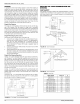
TABLE 12: Free Area
Minimum Free Area Required for Each Opening
BTUH Input Vertical Duct or
Rating Horizontal Duct Opening to Outside Round Duct
(2,000 BTUH) (4,000 BTUH) (4,000 BTUH)
75,000 37.5 in2 (193 cm2) 18.7 in2 (97 cm2) 5" (!3 cm)
100,000 50 in 2 (322 cm2) 25 in 2 (!61 cm2) 6" (15 cm)
EXAMPLE: Determining Free Area.
Appliance 1Appliance 2Total Input
100,000 + 30,000 = (130,000 + 4,000) = 32.5 Sq. In. Vertical
Appliance 1Appliance 2Total Input
100,000 + 30,000 = (130,000 + 2,000) = 85 Sq. In. Horizontal
TABLE 13: Unconfined Space Minimum Area in Square Feet
BTUH Input Rating Minimum Free Area Required for Each Opening
75,000 469 (43.57 m2)
100,000 625 (58.06 m2)
EXAMPLE: Square feet is based on 8 foot ceilings.
28,000 BTUH X 50 Cubic Ft. = 1,400 = !75 Sq. Ft.
1,000 8' Ceiling Height
18 Unitary Products Group