
Installation guide


66840/035-20003-001Rev.B(1205)
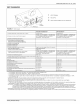
FAN ASSISTED FURNACE
FAN ASSISTED
L
f_
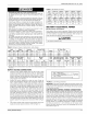
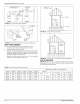
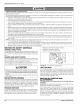
FIGURE 23: Typical Sidewall Vent Appiication
VENT PIPE
\
VENT
FLUE
BURNER
ACCESS
WALL PANEL
FIGURE 24: Typical Sidewall Vent and Termination Configuration
VENT PIPING ASSEMBLY
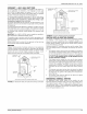
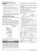
The final assembly procedure for the vent piping is as follows:
1. Cut piping to the proper length beginning at the furnace.
2. Deburr the piping inside and outside.
3. Dry-fit the vent piping assembly from the furnace to the termination
checking for proper fit support and slope. Piping should be sup-
ported with pipe hangers to prevent sagging. The maximum spac-
ing between hangers is 4 feet (1.22 m).
4. Assemble the vent piping from the furnace to the termination
securing the pipe connections with screws.
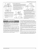
CHIMNEY OR
GAS VENT
OPENING
OPENING
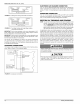
FIGURE 25: Typical Chimney Connections
FIGURE 26: Horizontal Air Inlet, Outlet and Chimney Connections
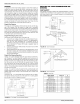
VENT CLEARANCES
IMPORTANT: The vent must be installed with the following minimum
clearances as shown in Figure 27 and must comply with state, regional,
and local codes and requirements.
TABLE 10: Horizontal Sidewall Venting Clearances
Heating
Input
BTU/H
75,000
75,000
100,000
Heating
Input
kW
22.0
22.0
29.5
Heating
Output
BTU/H
60,000
60,000
80,000
Heating
Output
kW
17.6
17.6
23.9
Furnace
Airflow
CFM
1200
1600
1600
Furnace
Airflow
cm/m
33.98
45.31
45.31
Horizontal Vent Length Ft. (m)with 4 Elbows
Pipe Size
Inches cm
4 10.16
4 10.16
4 10.16
Min. Vent Length
Feet meters
4.5 1.37
4.5 1.37
4.5 1.37
Max. VentLength
Feet meters
34.5 10.82
34.5 10.82
34.5 10.82
16 Unitary Products Group