
Installation guide
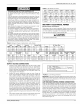


CATEGORY 1 - 450 F. MAX. VENT TEMR
The venting system must be installed in accordance with Section 5.3,
Air for Combustion and Ventilation, of the National Fuel Gas Code
Z223.1/NFPA 54 (latest edition), or Sections 7.2, 7.3 or 7.4 of CSA
B149.1, National Gas and Propane Codes (latest edition) or applicable
provisions of the local building code and these instructions.
The furnace shall be connected to any type of B, BW or L vent connec-
tor, and shall be connected to a factory-built or masonry chimney. The
furnace shall not be connected to a chimney flue serving a sepa-
rate appliance designed to burn solid fuel.
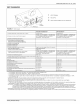
The furnace rating plate lists the maximum vent gas temperature. This
temperature must be used to select the appropriate venting materials
and clearances.
It is recommended that the appliance is installed in a location where the
space temperature is 32 °F (0°C) or higher. If the appliance is installed
in a location where the ambient temperature is below 32 °F (0°C), the
flue products could condense causing damage to the appliance heat
exchanger.
IMPORTANT: The "VENT SYSTEM" must be installed as specified in
these instructions for Residential Modular Homes.
This appliance may be common vented with another gas appliance for
residential installations as allowed by the codes and standards listed in
these instructions.
Modular Homes must be vented with an approved roof jack and may
not be common vented with other appliances.
VENTING
Category I venting consists of vertically venting one or more appliances
in B-vent or masonry chimney (as allowed), using single wall metal pipe
or B-vent connectors. Type B-vent system extends in a general vertical
direction and does not contain offsets exceeding 45 degrees. A vent
system having not more than one 60 degree offset is permitted.
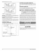
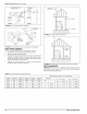
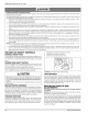
CHIMNEY OR
GAS VENT
VENTILATION LOUVERS
(each end of attic)
ALTERNATE
OUTLET
AIR
VENTILATION LOUVERS FOR UNHEATED CRAWL SPACE
FIGURE 21: Alternate Air Intake, Air Outlet and Chimney Connections
66840/035-20003-001 Rev. B (1205)
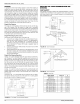
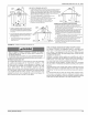
CH IMNEY OR
GAS VENT
VENTILATION LOUVERS
each end of attic)
OUTLET
AIR
INLET AIR DUCT
[ends 1 ft (30 cm)
above floor]
FIGURE 22: Air Inlet, Outlet and Chimney Connections
VENTING INTO AN EXISTING CHIMNEY
For Category I installations, the furnace shall be connected to a factory
built chimney or vent complying with a recognized standard, or a
masonry or concrete chimney lined with a material acceptable to the
authority having jurisdiction. Venting into an unlined masonry chimney
or concrete chimney is prohibited.
Whenever possible, B-1 metal pipe should be used for venting. Where
use of an existing chimney is unavoidable, the following rules must be
followed:
1. The masonry chimney must be built and installed in accordance
with nationa!ly recognized building codes or standards and must
be lined with approved fire clay tile flue liners or other approved
liner material that will resist corrosion, softening, or cracking from
flue gases. THIS FURNACE IS NOT TO BE VENTED INTO AN
UNLINED MASONRY CHIMNEY.
2. This furnace must be vented into a fire clay tile lined masonry
chimney only if a source of dilution air is provided, such as by com-
mon venting with a draft hood equipped water heater. If no source
of dilution air is available, Type B vent must be used, or masonry
chimney vent kit 1CK0603 or 1CKO6O4 must be used. Refer to the
instructions with the kit to properly apply these masonry chimney
kits.
3. The chimney must extend at least three feet above the highest
point where it passes through a roof of a building and at least two
feet higher than any portion of the building with a horizontal dis-
tance of ten feet.
4. The chimney must extend at least five feet above the highest
equipment draft hood or flue collar.
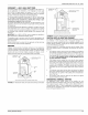
HORIZONTAL SIDEWALL VENTING
For applications where vertical venting is not possible, the only
approved method of horizontal venting is the use of an auxiliary power
vent. Approved power venters are Fields Controls Model SWG-4Y or
TjernIund Model GPAK-JT. Follow all application and installation details
provided by the manufacturer of the power vent. Refer to Figures 23
and 24 for typical installation views.
Unitary Products Group 15