
Installation guide


TWINNING DUCT SYSTEM
Twinned furnaces must only be applied on a common duct system. A
single air supply plenum must be used for both furnaces and coil(s).
Separate plenums and supply ducts systems cannot be utilized. A sin-
gle return air plenum, common to both furnaces must be used. It is sug-
gested that a return platform be utilized, with bottom air entrance into
each furnace. If a side entrance returns system is used, the common
return duct must be divided equally so as to supply each furnace with
an equal amount of return air.
Both furnaces must be identical models in both heating capacity and
CFM capacity. Both furnaces must be operated on the same motor
speed tap. See typical application, Figure 16.
If furnace staging is desired with two single stage furnaces on a com-
mon duct, where the gas burner on the first furnace operates on Wl
and the gas burner on the second furnace operates on W2, then the
use of an air-mixing device in the plenum to mix the air from both fur-
naces is strongly recommended. The mixing device must be installed
before any ducts that supply air to occupied spaces. Twinning causes
both indoor fans to operate simultaneously. If a mixing device is not
used, any ducts that are connected down stream from the furnace that
operates on W2, will be supplying cold air in the Heating mode to the
occupied spaces unless W2 is energized.
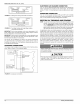
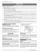
VENT PIPE
ELECTRICAL
SUPPLY
GAS SUPPLY
1COILFOR
EACH FURNACE
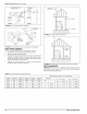
FIGURE 16: Typical Twinned Furnace Application
IMPORTANT: When two furnaces are twinned, typical system total air-
flow will be approximately 85% of additive individual furnaces, i.e., two
2000 CFM units will yield a total 3400 CFM.
IA CAUTION]
If a return duct is connected to only one furnace (with a connection
between the two furnaces) an imbalance in the airflow wil! occur
and the furnace furthest from the return plenum will overheat.
GAS PIPING
Furnace gas supplies must be provided as specified with these instruc-
tions. Since the furnaces are side by side, with no space between, gas
supplies must enter on the right and left respectively. All gas piping
must be in accordance with the national fuel gas code, ANSI Z223.1,
latest edition, and/or all local code or utility requirements.
66840/035-20003-001 Rev. B (1205)
TWINNING
Single-Wire Twinning
The control in the furnace has the single-wire twinning feature. With this
feature, a single wire is connected between the TWIN terminal on one
furnace board to the TWIN terminal on the second furnace board. The
board then communicates the blower status from one furnace to the
other along this wire. This communication makes the second furnace
blower come on at the same time, and on the same speed, as the first
furnace blower.
CAUTION1
The relay must not be installed in any location where it could be
exposed to water. If the relay has been exposed to water in any
way, it must not be used.
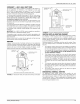
Single-Wire Twinning Instructions
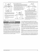
Connect the control wiring as shown in the Figure !7.
1. Connect the low voltage wiring from the wall thermostat to the ter-
minal strip on the control board of Furnace #1.
2. Connect a wire from the TWIN terminal of Furnace #! to the TWIN
terminal of Furnace #2.
3. Install a separate 24V relay as shown in the diagram below. Use of
this relay is required, as it ensures that the transformers of the two
furnaces are isolated, thus preventing the possibility of any safety
devices being bypassed.
Single-Wire Twinning Operation
Heating - On a call for heat (W signal) from the wall thermostat, both
furnaces will start the ignition sequence and the burners on both fur-
naces will light. About thirty seconds after the burners light, the blowers
on both furnaces will come on in heating speed. When the thermostat is
satisfied, the burners will all shut off and, after the selected blower off
delay time, both blowers will shut off at the same time. The twinned
controls ensure that both blowers come on and shut off at the same
time.
Cooling - On a call for cooling (Y signal) from the wall thermostat, both
furnace blowers will come on at the same time in cooling speed. When
the thermostat is satisfied, both blowers will stay on for 60 seconds,
then will shut off at the same time.
Continuous Fan - On a thermostat call for continuous fan (G signal),
both furnace blowers will come on at the same time in cooling speed
and will stay on until the G signal is removed.
FURNACEICONTROLBOARD FURNACE2CONTROLBOARD
TO A/C
WALL THERMOSTAT
FIGURE 17: Single Stage Twinning Wiring Diagram
Unitary Products Group 13