
Installation guide


66840/035-20003-001Rev.B(1205)
AkDANGER
PROPANE AND HIGH ALTITUDE CONVERSION KITS
It is very important to choose the correct kit and/or gas orifices for
the altitude and the type of gas for which the furnace is being
installed.
Only use natural gas in furnaces designed for natural gas. Only use
propane (LP) gas for furnaces that have been properly converted to
use propane (LP) gas. Do not use this furnace with butane gas.
Incorrect gas orifices or a furnace that has been improperly con-
verted will create an extremely dangerous condition resulting in pre-
mature heat exchanger failure, excessive sooting, high levels of
carbon monoxide, personal injury, property damage, a fire hazard
and/or death.
High altitude and propane (LP) conversions are required in order
for the appliance to satisfactory meet the application.
An authorized distributor or dealer must make all gas conversions.
In Canada, a certified conversion station or other qualified agency,
using factory specified and/or approved parts, must perform the
conversion.
The installer must take every precaution to insure that the furnace
has been converted to the proper gas orifice size when the furnace
is installed. Do not attempt to drill out any orifices to obtain the
proper orifice size. Drilling out a gas orifice will cause misallgnment
of the burner flames, causing premature heat exchanger burnout,
high levels of carbon monoxide, excessive sooting, a fire hazard,
personal injury, property damage and/or death.
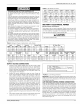
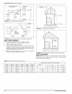
TABLE 7: High Altitude Conversion
Type Orifice at 2,000 ft. 3,000 ft. 4,000 ft. 5,000 ft.
Of Gas Sea Level (610 m) (914m) (1219 m) (1624 m)
Natural #42 #42 #43 #43 #43
Propane #54 #54 #55 #55 #55
Type 6,000 ft. 7,000 ft. 8,000 ft. 9,000 ft. 10,000 ft.
Of Gas (1829 m) (2134 m) (2438 m) (2743 m) (3048 m)
Natural #44 #44 #45 #46 #47
Propane #55 #55 #56 #56 #56
SECTION V: ELECTRICAL POWER
Electrical Power Connections
Field wiring to the unit must be grounded. Electric wires that are field
installed shall conform to the temperature limitation for 63°F (35°C) rise
wire when installed in accordance with instructions. Refer to Table 8 in
these instructions for specific furnace electrical data.
A. CAUTIONI
Use copper conductors only.
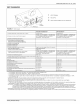
TABLE 8: Ratings & Physical / Electrical Data - Upflow Models
Input
MBH kW
75 22.0
75 22.0
100 29.3
Input
MBH kW
75 22.0
75 22.0
100 29.3
Output
MBH kW
60 17.6
60 17.6
80 23.4
Max. Outlet
Air Temp
°F °C
!65 73.9
160 7! .1
!70 76.7
Nominal
CFM cmm
1200 34.0
1600 45.3
1600 45.3
Blower
Hp Amps
!/3 6.2
1/2 6.2
!/2 7.0
Cabinet Width Air Temp. Rise
In. cm AFUE °F °C
16 7/8 44.45 80.0 35-65 19.4-36.1
20 53.34 80.0 30-60 16.7-33.3
20 53.34 80.0 40-70 22.2-38.9
Blower Total Max Over-current Min.
Size Unit Size (awg) @ 76 ft. Wire
In. cm amps protect one way
10x8 25.4 x 20.3 6.7 15 14
10x!0 25.4 x 25.4 8.5 15 14
10x!0 25.4 x 25.4 8.5 15 14
Wire size and over current protection must comply with the National Electrical Code (NFPA-70-1atest edition) and all locaI codes.
AFUE 80%.
Operation Operation
WGT. WGT.
LBS Kg
1!6 53.5
129 58.5
135 61.2
SUPPLY VOLTAGE CONNECTIONS
1. Provide a power supply separate from all other circuits. Install
overcurrent protection and disconnect switch per local/national
electrical codes. The switch should be close to the unit for conve-
nience in servicing. With the disconnect or fused switch in the OFF
position, check all wiring against the unit wiring label. Refer to the
wiring diagram in this instruction.
2. Remove the screws retaining the wiring box cover. Route the
power wiring through the opening in the unit into the junction box
with a conduit connector or other proper connection. In the junc-
tion box there will be three wires (a Black Wire, a White Wire and a
Green Wire). Connect the power supply as shown on the unit-wir-
ing label on the inside of the blower compartment door or the wir-
ing schematic in this section. The black furnace lead must be
connected to the L1 (hot) wire from the power supply. The white
furnace lead must be connected to neutral. Connect the green fur-
nace lead (equipment ground) to the power supply ground. An
alternate wiring method is to use a field provided 2" (5.1 cm) x 4"
(10.2 cm) box and cover on the outside of the furnace. Route the
furnace leads into the box using a protective bushing where the
wires pass through the furnace panel. After making the wiring con-
nections replace the wiring box cover and screws. Refer to Figure
12.
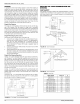
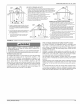
3. The furnace's control system requires correct polarity of the power
supply and a proper ground connection. Refer to Figure 12.
B ._ BL_O_]
_WHT (NEUTRAL) j, NOMINAL120VOLT
GRN _..GRN
FIGURE 12: Line Wiring Connections
IMPORTANT: The power connection leads and wiring box may be relo-
cated to the left side of the furnace. Remove the screws and cut wire tie
holding excess wiring. Reposition on the left side of the furnace and fas-
ten using holes provided.
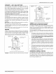
LOW VOLTAGE CONTROL WIRING CONNECTIONS
Install the field-supplied thermostat by following the instructions that
come with the thermostat. With the thermostat set in the OFF position
and the main electrical source disconnected, connect the thermostat
wiring from the wiring connections on the thermostat to the terminal
board on the ignition module, as shown in Figure 13. Electronic thermo-
stats may require the common wire to be connected as shown with the
dashed line in Figure 13. Apply strain relief to thermostat wires passing
through cabinet. If air conditioning equipment is installed, use thermo-
stat wiring to connect the Y and C terminals on the furnace control
board to the yellow and brown wires on the condensing unit (unit out-
side). Refer to Figure 13.
Unitary Products Group 11