
Installation guide


66840/035-20003-001Rev.B(1205)
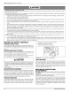
Room Furnace Condensing
Thermostat Control Unit
ToAir Conditioner
Controls
_, ......................
_. ......................
Common Trst at Connection
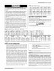
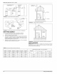
FIGURE 13: Heating and Cooling Thermostat Connections
Room Furnace Condensing
Thermostat Control Unit
ConO,ti......
....... !!!!!!!!!!!!!!!!!!!
FIGURE 14: Two-Stage Cooling and Single Stage Heating
Thermostat Connections
IMPORTANT: Set the heat anticipator in the room thermostat to 0.45
amps. Setting it lower will cause short cycles. Setting it higher will cause
the room temperature to exceed the set points.
IMPORTANT: Some electronic thermostats do not have adjustable heat
anticipators. They may have other type cycle rate adjustments. Follow
the thermostat manufacturer's instructions.
The 24-volt, 40 VA transformer is sized for the furnace components
only, and should not be connected to power auxiliary devices such as
humidifiers, air cleaners, etc. The transformer may provide power for an
air conditioning unit contactor.
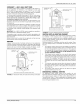
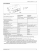
ACCESSORY CONNECTIONS
The furnace control will allow power-switching control of various acces-
sories. Refer to Figure !5 for connection details.
115 VOLT
HUMID F ER
EAC HOT
HUM. HOT
BLK
115 VOLT
ELECTRONIC
A R CLEANER
HE_MSWITCHED
CIRCUITS
HUMI NEUTRALS
ELECTRONIC AIR CLEANER CONNECTION
Two 1/4" (0.6 cm) spade terminals (EAC and EAC N) for electronic air
cleaner connections are located on the control board. The terminals
provide 115 VAC (1.0 amp maximum) during circulating blower opera-
tion.
HUMIDIFIER CONNECTION
Two 1/4" (0.6 cm) spade terminals (HUM and HUM N) for humidifier
connections are located on the control board. The terminals provide 115
VAC (1.0 amp maximum) during heating system operation.
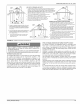
SECTION Vh TWINNING AND STAGING
NOTE: You can twin two furnaces that have the same integrated control
module. Check the part number on the integrated control mod-
ule. You _ two furnaces that have different integrated
control module part numbers. If the part numbers of the two inte-
grated control modules are different they may not communicate
with each other so they will not work in a twinning application.
In applications where more heating capacity or more airflow capacity is
needed than what one furnace can deliver, twinning can be used to
make two furnaces operate in tandem. When two furnaces are installed
using the same duct system, it is very important that the two furnace cir-
culating air blowers operate in unison. If one blower starts before the
second blower, the duct system will become pressurized and the blower
on the second furnace will turn backwards causing the second furnace
to overheat, resulting in damage to the furnace. Twinning is used to
make two furnaces operate in tandem, using one duct system, one
room thermostat and causing both furnaces to turn on and off simulta-
neously.
AWARNING
Before installing the relay and wiring, disconnect electrical power to
both furnaces. Failure to cut power could result in electrical shock
or equipment damage.
CAUTIONI
The relay must not be installed in any location where it could be
exposed to water If the relay has been exposed to water in any
way, it must not be used.
FIGURE 15: Accessory Connections
12 Unitary Products Group