Gas Barbecue Use, Care & Assembly Manual With Grill Lighting Instructions Model 9947A726 ASSEMBLER/INSTALLER: Leave these instructions with the consumer. CONSUMER/USER: Read all instructions and keep in a safe place for future reference. IMPORTANT Read this manual carefully before assembling, using or servicing this grill. Keep this manual for future reference. If you have questions about assembly, operation, servicing or repair of this grill, please call Coleman at 1-800-835-3278 or TDD: 316-832-8707.
WARNING Contents General Safety Information. . . . . . . . . . . . . . . . . . . . . . . . . . . . . . . . . . . . . 2 General Installation. . . . . . . . . . . . . . . . . . . . . . . . . . . . . . . . . . . . . . . . . . . 3 Electrical Attachments . . . . . . . . . . . . . . . . . . . . . . . . . . . . . . . . . . . . . . . . 4 LP Fuel Connections Other Than Portable L.P. Cylinders . . . . . . . . . . . . . 4 Natural Gas Connections . . . . . . . . . . . . . . . . . . . . . . . . . . . . . . . . . . . .
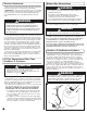
General Safety Information (cont.) 1 3 2 4 7 24" 8 5 6 General Installation • Installation must conform with local codes or, in the absence of local codes, with either the National Fuel Gas Code, ANSI Z223.1 (USA), CAN/CGA-B149.1, Natural Gas Installation Code or CAN/CGA-B149.2, Propane Installation Code (Canada). To check local codes, see your local L.P. gas dealer or natural gas company listed in the Yellow Pages for recommended installation procedures and regulations.
Electrical Attachments When using an electric attachment with grill, follow specification and warning statements accompanying the attachment. IMPORTANT: If using an external electrical source, the installed appliance must be electrically grounded according to local codes or, in the absence of local codes, with the National Electrical Code, ANSI/NFPA 70 or the Canadian Electrical Code CSA C22.1.
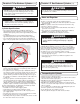
Portable L.P. Gas Barbecue Cylinders (cont.) DANGER • DO NOT insert any foreign objects into the valve outlet. You may damage the valve. A damaged valve can cause a leak, which could result in explosion, fire, severe personal injury or death. WARNING • Cylinders must be stored outdoors out of the reach of children and must not be stored in a building, garage or any other enclosed area. (Fig. 11) Cylinder Specifications • Any L.P.
Transporting the Cylinder (cont.) Filling and Purging Type 1 L.P. Gas Cylinders (cont.) WARNING Handle a full cylinder with care. Gas is under high pressure. 13 CGA-510 POL DANGER • NEVER store a spare L.P. gas supply cylinder under the grill body or inside grill enclosure or in the vicinity of any heat producing appliance. (Fig. 12) • NEVER fill the cylinder beyond 80% full. Failure to follow this information exactly could result in an explosion and/or fire causing death or serious injury.
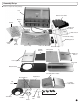
Assembly/Set up ■ Remove components from package.
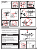
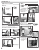
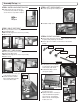
Assembly/Set up (cont.) STEP 1 BOTTOM & SIDE PANELS ■ Install three screws from the top and three Hex nuts from below as shown for each side panel. ■ Tighten screws. Panel with hole must be installed as shown. 6 Required STEP 4 TOP PANEL 6 Required ■ Set Top Panel into position on top of Middle Divider. ■ Align holes and handinstall 2 screws. ■ Install screws where Top Panel joins to Sides. ■ Tighten screws. STEP 5 BACK PANEL ■ Install Back Panel as shown.
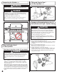
Assembly/Set up (cont.) STEP 6 INSTALLING IGNITION BOX ■ Install the Ignition Box to the left front leg (on the inside surface) with two self-tapping screws. Two holes are provided for location. STEP 8 LEFT SIDE BURNER (cont.) ■ Insert the post through the mounting hole. 2 Required ■ Reinstall the hairpin cotter. STEP 7 RIGHT SIDE TABLE ■ Remove preinstalled screws from Right Supports. ■ Install Right Side Table. NOTE: Side Table Supports have slots for easy assembly. ■ Tighten securely.
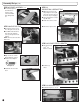
Assembly/Set up (cont.) STEP 11 GREASE PAN & GREASE TRAY STEP 9 BURNER ASSEMBLY (cont.) ■ The cardboard packing below the burners cannot be easily removed. It will burn away during the first use. ■ Note: Remove Grease Tray and packing from rear of grill. (This is the storage position of the Grease Tray for shipping.) Grease Tray ■ Grease Pan attaches to Grease Tray with slides. ■ Install Grease Pan as shown. Grease Pan STEP 10 HOSE ROUTING ■ Route Burner Valve at end of Hose through hole in cart end.
Assembly/Set up (cont.) STEP 14 BURNER TRIVET STEP 18 DOORS ■ Open Left Side Burner Lid and place Trivet on Burner. ■ Install Left and Right Doors. ■ Insert Bottom Door Pin into hole on Bottom Frame. ■ Hinge Pins are spring-loaded. Pull down to insert Hinge Pin into Top Frame Hole. NOTE: Make sure the 2 holes on each Door are at the top when installed. Top Frame Bottom Frame Hole STEP 15 TOOL HOLDERS 4 Required Bottom Door Pin ■ Install Tool Holders onto front of Left Side Burner and Right Side Table.
Assembly/Set up (cont.) Connecting Type 1 L.P. Gas Cylinders STEP 20 ROTISSERIE (cont.) WARNING ■ Install Rotisserie Motor & Rotisserie Spit as shown. ■ Make sure Rotisserie Motor is placed on the right side of the grill. NOTE: The Rotisserie Motor will appear to be upside down when installed correctly. This procedure MUST be performed OUTDOORS only! Be sure L.P. cylinder valve is closed. Attach to Grill. Read and follow directions on the cylinder and fuel hose safety tags.
Leak Testing (cont.) Start-Up Check List WARNING How to Check for Leaks 1. Make a soapy solution of equal parts mild liquid dishwashing detergent and water. 2. Turn off all burner control knobs. 3. Turn on fuel supply. Turn cylinder valve knob counterclockwise (right to left) one rotation. 4. Apply soap solution to connections indicated with arrows in Fig. 16. If bubbles appear at these areas, a leak is indicated.
Lighting Instructions (cont.) Lighting Main Burners (cont.) 18 3 4 Match-Lighting 1. Strike and place the burning match near the BURNER being operated. 2. Turn on BURNER CONTROL KNOB while holding match near burner. 3. The other burners can be ignited by turning them on one at a time after first burner is lighted. CAUTION Use a LONG wooden match. Make sure all burner controls are off except one being lighted. 1 2 Lighting Side Burner 1. Turn on side burner gas control knob. (Fig. 20) 2.
Shutting Off the Grill (cont.) 1. Turn all burner control knob(s) to off. 2. After burner flame goes out, turn off fuel supply. For an L.P. cylinder, turn the L.P. cylinder knob in a clockwise direction until it stops. CAUTION General Use and Correct Burner Flames (cont.) 21 Yellow Good Bad Be certain the gas is shut off at the L.P. cylinder valve anytime the grill is not in use.
In Case of Grease Fire Follow These Steps: 1. Shut off gas at the burner valve(s) and stay away! 2. Allow the fire to burn itself out. 3. Once the fire is out and the appliance has cooled, shut off the L.P. cylinder valve. 4. Clean all parts and inspect for damage. Parts to check for damage are the L.P. cylinder, cylinder valve, regulator, gas supply hose, burner valve(s) and burner(s). 5. If any of the above mentioned components are damaged, seek replacement from Coleman before operating the grill again.
Cleaning and Maintenance (cont.) Troubleshooting • COOKING GRIDS: Clean cooking grids with mild soap and hot water. Remove stubborn residue with a mild cleanser or scrub brush. Use a brass-bristle brush on porcelain-coated grids. DO NOT use a commercial oven cleaner. Problem: Burner will not light or has incomplete burner flame. • PORCELAIN-COATED HEAT TENTS: Wipe off grease residue using a cleaning pad and a brass-bristle brush to knock off residue. Use care not to damage porcelain finish.
Troubleshooting (cont.) For Your Additional Safety (cont.) Problem: Flame behind control panel or control knob area. IF YOU STILL HAVE A PROBLEM, THERE MAY BE AIR IN THE CYLINDER DUE TO IMPROPER PURGING. Possible Causes and Solutions: 2. The L.P. cylinder was not properly purged before it was filled. SOLUTION: See your L.P. gas supplier. IMMEDIATELY shut off cylinder valve and allow grill to cool. 1. Check for spider webs or insect nests in venturi and clean venturi. 2.
Replacement Parts List Item 1 2 3 4 5 6 7 8 9 10 11 12 13 14 15 Part No.
Warranty COLEMAN GAS BARBECUE GRILL LIMITED WARRANTY FOR 6000 SERIES GRILLS The Coleman Company, Inc. (“Coleman”) warrants that the following parts of this product will be free from defects in material and workmanship for the following time periods: the castings and burners carry a limited lifetime warranty; the electronic ignition components are warranted for ten (10) years; and the other components, except for the propane cylinder and paint finish, are warranted for five (5) years.