
Installation guide


129098-UIM-H-1011
SECTION
IV:
FILTERS
FILTER
INSTALLATION
All
applications
require
the
use
of
a
filter.
A
standard
air filter
is
located
in
the
return
filter
rack
on
the
louvered
door.
The
air
filter(s)
must
be
replaced
with
air
filter(s)
that
are
the
same
size
and
same
type.
Replacement
filter
size
is
shown
in
Table
3.
A
CAUTION
All
installations
must
have
a
filter
installed.
Downflow
Filters:
There
are
two
types
of
downflow
filter
racks.
1.
FURNACE
FILTER
RACK:
A
return
filter
rack
with
two
standard
throwaway
type
filters
are
supplied
on
ail
models.
The
return
filter
rack
is
located
on
the
inside
of
the
louvered
door.
This
type
of
filter
rack
is
designed
for
two
standard
air
filters
only.
Pleated
Media
or
Washable
Filters
cannot
be
used
in
this
filter
rack
because
they
cause
too
much
pressure
drop
causing
a
reduction
in
airflow.
Refer
to
Figure
13.
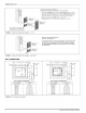
EXTERNAL RETURN
FILTER
GRILLE:
The
second
type
is
an
external
return
air filter
grille
that
can
only
be
used
in
applica-
tions
where
the
furnace
is
installed
in
a
closet.
This
type
of
fil-
ter
grille
is
typically
installed
in
a
closet
door
or
wail
with
the
filters
located
within
12"
(30.5
cm)
of
the
return
air
opening
of
the
fur-
nace.
There
musi
be
a
minimum
clearance
of 6"
(15.2
cm)
between
the front
of
the
furnace
and
the
closet
door
and/or
the
fur-
nace
and
the
filter
grille
to
prevent
the
return
air
flow
from
being
obstructed.
Refer
to
Table
1
Unit
Clearances
to
Combustibles.
NOTE:
Remove
air
filters
inside
louvered
door
when
using
an
external
filter
grille.
N
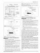
TABLE
3:
Filter
Sizes
-
All
Models
a.
if
the
standard
throwaway
filter
are
used
the
external
filter
grille
must
have
a
minimum
area
of
540
in?
(3483
cm?)
which
would
equal
a
15"
X
36"
filter
grille.
b.
if
the
Pleated
Media
or
Washable
Filters
are
used
the
exter-
nal
filter
grille
must
have
a
minimum
area
of
684
in?
(4413
cm?)
which
would
equal
a
18"
X
38"
filter
grille.
The
increased
area
is
to
reduce
the
pressure
drop
across
the
air
filter.
c.
Consideration
should
be
given
when
locating
the
return
filter
grille
for
maintenance.
d.
Any
filter
that
has
a
large
pressure
drop
should
be
checked
to
be
sure
the
pressure
drop
caused
by the
air filter
will
not
pre-
vent
the
furnace
from
operating
within
the
rise
range,
speci-
fied
on
the
rating
plate
and
in
Table
7.
If
the
furnace
does
not
operate
within
the
specified
rise
range
then
a
larger
air filter
or
an
air filter
that
has
a
lower
pressure
drop
must
be
installed.
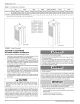
Air
Filters
Can
Be
Found
On
The
Inside
Of
This
Panel
FIGURE
13:
Furnace
Air
Filters
Input
Output
Air
Flow
Cabinet
Width
Door
Filtert
MBH
kw
MBH
kW
CFM
cmm
In In
cm
56
16.4
44.8
13.4
1305
34.0
19
3/4
2-16x20x1
2x41x51
70
20.5
56
16.4
1305
34.0
19
3/4
2-16x20x1
2x41x51
77
22.5
62
18.4
1305
34.0
19
3/4
2-16x20x1
2x41x51
90
26.3
72
21.4
1305
34.0
19
3/4
2-16x20x1
2x41x51
1.
All
Models
shipped
with
disposable
filters
mounted
inside
upper
furnace
door.
2.
Pleated
filters
have
high
pressure
drop
and
require
cleaning every
60
days.
3.
Dirty
filters
can
cause
excess
heating
bills,
lower
air
flow,
and
reduce
heat
exchanger
life.
SECTION
V:
GAS
LINE
INSTALLATION
GAS
SAFETY
ADANGER
This
furnace
is
designed
to
operate
on
NATURAL
GAS
or
PRO-
PANE
GAS
ONLY.
Do
Not
Burn
any
other
Fuel
in
this
furnace.
Burning
any
fuel
except
NATURAL
GAS
or
PROPANE
GAS
can
cause
premature
heat
exchanger
burnout,
high
levels
of
carbon
monoxide,
excessive
sooting,
a
fire
hazard,
personal
injury,
prop-
erty
damage
and
/or
death.
ADANGER
An
overpressure
protection
device,
such
as
a
pressure
regulator,
must
be
installed
in
the
gas
piping
system
upstream
of
the
furnace
and
must
act
to
limit
the
downstream
pressure
to
the
gas
valve
so
it
does
not
exceed
0.5
PS!
(14”"
w.c.
(3.48
kPa).
Pressures
exceeding
0.5
PSI
(14”
w.c.
(3.48
kPa)
at
the
gas
valve
will
cause
damage
to
the
gas
valve,
resulting
in
a
fire
or
explosion
or
cause
damage
to
the
furnace
or
some
of
its
components
that
will
result
in
property
damage
and
loss
of
life.
GAS
PIPING
Installation
and
Checking
of
Gas
Line
Gas
Supply
piping
must
be
sized
in
accordance
with
the
recommenda-
tions
contained
in
National
Fuel
Gas
Code
(ANSI-2223.1,
NFPA-54)
unless
local
codes
or
regulations
state
otherwise.
Materials
used
and
pipe
sizing
for
U.S.
manufactured
homes
must
com-
ply
with
requirements
contained
in
Manufactured
Homes
A119.1,
Rec-
reational
Vehicles
A119.2
and
H.U.D.
Title
24,
Section
3280.705
and
any
local
or
state
codes.
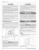
NOTE:
The
gas
line
inlet
on
the
gas
valve
is
1/2-14
N.P.T.
The
gas
line
may
be
installed
through
the
furnace
floor
or
furnace
side
to
the
gas
valve.
A
CAUTION
If
the
gas
input
to
the
furnace
is
too
great
because
of
excessive
gas
pressure,
wrong
size
orifice,
high
altitude,
etc.,
the
burner
flame
will
be
sooty
and
may
produce
carbon
monoxide,
which
could
result
in
unsafe
operation,
explosion,
and/or
fire
or
asphyxiation.
Johnson
Controls
Unitary
Products