
Installation guide


129098-UIM-H-1011
NOTE:
See
label on
coil
panel
for
conversion
and
lighting
instructions.
Obtain
a
temperature
rise
within
the
ranges
specified
on
the
name
plate.
/
AUTOMATIC
DAMPER
SUPPLY:
DUCT:
OPENING
FURNACE
BASE
DUCT
CONNECTOR
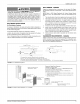
NOTE:
FOR
BEST
AIR
DELIVERY
INSTALL
DAMPER
WITH
BLADES
PARALLEL
TO
SUPPLY
DUCT.
FIGURE
11:
Anti-Backflow
Damper
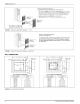
INSTALLATION
RECOMMENDATIONS
1.
Remove
the
front
panels
and
set the
furnace
onto
the
duct
con-
nector.
Slide
it
back
until
the
rear
of
the
unit
engages
the
locator
bracket.
2.
Secure
the
front
of
the
furnace
with
two
screws
at
the
mounting
holes
provided.
3.
Secure
the
top
of
the
furnace
to
a
structural
member
using
screw
through
the
strap
at
the
back
of
the
furnace.
Strap
may
be
moved
to
any
of
the
holes
located
along
the top
back
of
the
furnace.
Installer
may
provide
an
equivalent
method,
such
as
screws
through
the
casing
side.
The
duct
system
is
a
very
important
part
of
the
installation.
If
the
duct
system
is
improperly
sized
the
furnace
will
not
operate
properly.
The
ducts
attached
to
the
furnace
plenum,
should
be
of
sufficient
size
so
that
the
furnace
operates
at
the
specified
external
static
pressure
and
within
the
air
temperature
rise
specified
on the
nameplate.
Consideration
should
be
given
to
the
heating
capacity
required
and
also
to
the
air
quantity
(CFM)
required.
These
factors
can
be
determined
by
calculating
the
heat
loss
and
heat
gain
of
the
home
or
structure.
If
these
calculations
are
not
performed
and
the
furnace
is
over-sized,
the
follow-
ing
may
result:
1.
Short
cycling
of
the
furnace.
2.
Wide
temperature
fluctuations
from
the
thermostat
setting.
3.
Reduced
overall
operating
efficiency
of
the
furnace.
The
supply
and
return
duct
system
must
be
of
adequate
size
and
designed
such
that
the
furnace
will
operate
within
the
designed
air
tem-
perature
rise
range
and
not
exceed
the
maximum
designed
static
pres-
sure.
These
values
are
listed
in
Table
2.
SECTION
Ill:
RETURN
AIR
REQUIREMENTS
CLOSET
INSTALLATIONS
Additional
Requirements
Additional
requirements
for
floor
and
ceiling
return
system
for
closet
installed
sealed
combustion
heating
appliance
are
given
in
the
next
paragraph.
_AWARNING
HAZARD
OF
ASPHYXIATION,
DO
NOT
COVER
OR
RESTRICT
FLOOR
OPENING.
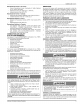
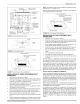
TABLE
2:
External
Static
Pressure
Range
Nominal
Ext.
Static
Pressure
Input
Output
.
4
—
-
Air
Flow
Minimum
Maximum
MBH]
kW
|MBH]|
kW
|CFM|cmm|In.W.C|
kPa
|In.W.C]
kPa
56
116.4]
45
112.9
|1305)/36.9
0.10
|0.0249)
0.30
|
0.0747
70
|20.5]
56
[16.4
|1305/36.9
0.10
|0.0249)
0.30
|
0.0747
77
122.5]
62
|18.0
|1305/36.9
0.10
|0.0249)
0.30
|
0.0747
90
|}26.3})
72
121.1
|1305/36.9
|0.10
|0.0249)
0.30
|
0.0747
1.
Std.
Blower-High
Speed-No
Coil.
IMPORTANT
The
air
temperature
rise
should
be
taken
only
after
the
furnace
has
been
operating
for
at
least
715
minutes.
Temperatures
should
be
taken
6”
(15.2
cm)
past
the
first
bend
from
the
furnace
in
the
supply
duct.
The
return
air
temperature
must
be
taken
at
the
return
air
lou-
vered
door.
Return
static
pressures
can
be
taken
by
pushing
probe
through
the
air
filter
on
the
louvered
door.
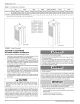
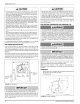
BLEND
AIR
INSTALLATIONS
If
a
blend
air
ventilation
system
is
installed,
the
5”
(12.7
cm)
diameter
knockout
in
the top
cover
must
be
removed.
The
blend
air
damper
is
to
be
placed
on
the
top
cover
and
secured
with
screws
as
shown
in
Figure
12.
The
power
wires
for
the
Blend
Air
Damper
are
inserted
through
the
7/8”
(2.22
cm)
hole
in
the top
cover.
The
wires
to
the
Blend
Air
Damper
will
be
connected
as
shown
in
Figure
20.
Refer
to
the
Blend
Air
Installa-
tion
Manual
to
complete
the
installation.
:
BLEND
AIR
FLEX
DUCT
BLEND
AIR
DAMPER
FIGURE
12:
Floor
Installation
Johnson
Controls
Unitary
Products