
Installation guide


129098-UIM-H-1011
REAR
WALL
OF
ENCLOSURE
CEILING
CUT-OUT
FOR
ROOF
JACK
2.314
(7.0
om)
FLOOR
CUT-OUT
FOR
DUCT
CONNECTOR
I
~
ct
€|35
T
5
|
FURNACE
on
| I
OUTLINE
2
5
t
In
+
soo
€
8
2
we
\
|
s
1
|
8
15
|
a
_
ti
38tem)>|
|
OPTIONAL
GAS
|
1
C¥
T
OR
ELECTRIC
| |
ENTRANCE
2-1/8
(5.4.0m)
|
FRONT
PANEL
=
*
C*--4aq6=
7
OF
FURNACE
t
I
4-3/8
-
6-3/8]
4-1/8
(3.5
om)
pe
om)
|
3-4
jl
(2.9
cm)
}—
9-3/4
—}
(83cm)
FUTURE
;
24.8
REFRIGERANT
om)
20
»
FLOOR
LINE
ENTRANCE
(50.8
cm)
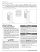
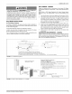
FIGURE
7:
Recommended
Floor
Cut-out
FLOOR
—_—“
|
FLOOR
DUCT
CONNECTOR
a
DEPTH
la
JOIST
SUPPLY
DUCT
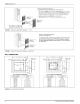
FIGURE
8:
Duct
Connector
Depth
pore
LOCATOR
BRACKET
fe
NAILS,
FLAT
HEAD
SCREWS
/
OR
STAPLES
SCREWS
g
\
SUPPLY
DUCT
FIGURE
9:
Duct
Connector
Screw
Attachment
INSTALLATION
OF
SCREW
ATTACHMENT
DUCT
CONNECTOR
1.
Make
floor
cut
out
as
shown
in
Figure
7.
2.
Determine
the
depth
of
the
floor
cavity
from
the
surface
of
the
floor
to
the top
of
the
supply
air
duct
and
select
the
appropriate
duct
connector
from
the
chart.
See
Figures
6
and
8.
3.
Place
locating
bracket
(supplied
with
the
duct
connector)
to
the
back
edge
of
the
floor
opening.
See
Figure
9.
4.
Apply
a
water
based
duct
sealant
to
the
1/2"
supply
duct
attach-
ment
flange
of
the
duct
connector.
5.
Determine
which
of
the
four
positions
the
duct
connector
best
cen-
ters
over
the
supply
duct
and
insert
it
through
the
floor
cut-out.
6.
When
properly
aligned
with
the
supply
duct,
secure
the
duct
con-
nector
to
the
floor
with
nails,
flat
head
screws
or
staples.
7.
Use
screws
as
required
to
secure
the
duct
connector
to
the
supply
duct.
8.
Cutout
the
opening
to
the
supply
duct.
If
sealant
was
not
used,
the
installer
should
tape
the
mating
flanges
to
provide
a
good
air
seal.
NOTE:
Duct
sealant
and
tape
must
be
classified
as
meeting
HUD
Stan-
dard
3280.715,
U.L.
Standard
181A.
If
tape
is
used
to
provide
a
better
air
seal,
it
should
be
a
type
approved
by the
applicable
national
or
local
codes.
y-—
LOCATOR BRACKET
/
NAILS,
FLAT
HEAD
SCREWS
/
OR
STAPLES
/
BEND
TABS
UNDER
/
DUCT
OPENING
TO
/
«¢
6
SECURE
TO
THE
yi
t
SUPPLY
DUCT.
\
SUPPLY
DUCT
|
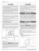
FIGURE
10:
Duct
Connector
Tab
Attachment
INSTALLATION
OF
TAB
ATTACHMENT
DUCT
CONNECTORS
1.
Make
floor
cut
out
as
shown
in
Figure
7.
2.
Determine
the
depth
of
the
floor
cavity
from
the
surface
of
the
floor
to
the top
of
the
supply
air
duct
and
select
the
appropriate
duct
connector
from
the
chart.
See
Figures
6
and
8.
3.
Place
locating
bracket
(supplied
with
the
duct
connector)
to
the
rear
of
the
floor
area
for
the
furnace.
See
Figure
10.
4.
Determine
which
of
the
four
positions
the
duct
connector
best
cen-
ters
over
the
supply
duct
and
insert
it
through
the
floor
cut-out.
5.
Mark
cut-out
location
on
the
supply
duct
and
remove
the
duct
con-
nector.
6.
Cut
out
the
opening
to
the
supply
duct.
7.
Bend
tabs
down
through
and
back
up
under
the
supply
duct.
8.
Secure
the
duct
connector
to
the
floor
with
nails,
flat
head
screws
or
staples.
The
duct
connector
is
designed
for
use
on
ducts
down
to
12”
in
width.
When
using
the
connector
on
smailer
width
ducts,
there
will
not be
suffi-
cient
clearance
to
bend
the
tabs
on
two sides
of
the
duct
connector.
In
such
cases
the
tabs
may
be
attached
to
the
sides
of
the
duct
by
using
sheet
metal
screws
or
other
suitable
fasteners.
Holes
for
sheet
metal
screws
are
provided
in
three
(3)
tabs
on
each
side
of
the
duct
connector.
If
more
than
3
tabs
need
to
be
used
to
provide
a
more
secure
and
air
tight
connection,
the
remaining
tabs
can
also
be fas-
tened
to
the
duct
with
screws
after
drilling
the
required
screw
hole.
Furnace
and
Air
Conditioner
Installations
if
an
air
conditioner
is
installed
which
does
not
use
the
blower
for
air
dis-
tribution
and
operates
completely
independent
of
the
furnace,
the
ther-
mostat
system
must
have
an
interlock
to
prevent
the
furnace
and
air
conditioner
from
operating
at
the
same
time.
This
interlock
system
usu-
ally
contains
a
heat-cool
switch
which
must
be
turned
to
either
HEAT
or
COOL
to
activate
either
heating
or
cooling
operation,
or
a
positive
OFF
switch
on the
cooling
thermostat.
When
used
in
connection
with
a
cooling
unit
the
furnace
shall
be
installed
parallel
with
or
on the
upstream
side
of
the
cooling
unit
to
avoid
condensation
in
the
heat
exchanger.
For
installations
with
a
parallel
flow
arrangement,
the
furnace
must
be
equipped
with
a
damper
to
prevent
cold
air
from
being
discharged
up
around
the
heat
exchanger.
Cold
air
causes
condensation
inside
the
exchanger
and
can
cause
it
to
rust
out
which
can allow
products
of
combustion
to
be
circulated
into
the
living
area
by the
furnace
blower
resulting
in
possible
asphyxiation.
An
air
flow
activated
automatic
damper,
P/N
7900-6771,
is
available
from
furnace
manufacturer.
See
Figure
11.
Johnson
Controls
Unitary
Products