
Installation guide


129098-UIM-H-1011
|
AWARNING
The
supply
air
temperature
MUST
NEVER
exceed
the
Maximum
Supply
Air
Temperature,
specified
on the
nameplate.
Operating
the
furnace
above
the
maximum
supply
air
temperature
will
cause
the
heat
exchanger
to
overheat,
causing
premature
heat
exchanger
failure.
Improper
duct
sizing,
dirty
air
filters,
incorrect
manifold
pressure,
incorrect
gas
orifice
and/or
a
faulty
limit
switch
can
cause
the
furnace
to
operate
above
the
maximum
supply
air
temperature.
Refer
to
sections
II,
Ill
and
XI
for
additional
informa-
tion
on
correcting
the
problem.
DUCTWORK
INSTALLATION
Air
Distribution
Systems
For
proper
air
distribution,
the
supply
duct
system
shall
be
designed
so
that
the
static
pressure
does
not
exceed
the
listed
static
pressure
rating
on
the
furnace
rating
plate.
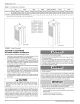
Three
typical
distribution
systems
are
illustrated
in
Figure
2.
Location,
size
and
number
of
registers
should
be
selected
on
the
basis
of
best
air
distribution
and
floor
plan
of
the
home.
The
Air
Temperature
Rise
is
to
be
adjusted
to
obtain
a
temperature
rise
within
the
range(s)
specified
on
the
furnace
rating
plate.
DUCT
DESIGN
-
CANADA
Supply
duct
design
shall
be
in
accordance
with
the latest
HRA
Digest,
the
ASHRAE
Handbook
Fundamentals,
or
other
good
engineering
prin-
ciples.
NOTE:
Refer
to
HRA
Digest
Residential
Air
System
Design
Manual,
Sections
5
and
6,
the
requirements
of
which
are
summarized
as
fol-
lows:
1.
The
kilowatt
output
of
each
duct
register
shall
not
exceed
2.35
kW.
2.
The furnace
output
should
not be
more
than
20%
greater
than
the
calculated
heat
loss
of
the
home.
If
a
larger
furnace
is
used,
the
duct
system
shall
be
capable
of
the
increased
air
volumes
neces-
sary
to
maintain
a
maximum
air
temperature
rise
of
50°
C
as
the
air
passes
over
the
furnace
heat
exchanger.
3.
Atleast
one
warm
air
supply
outlet
shall
be
provided
in
each
room.
4.
When
rooms
are
located
adjacent
to
the
exterior
walls,
warm
air
outlets
shall
be
located
so
as
to
bathe
at
least
one
exterior
wail
and,
where
practical,
a
window
area
with
warm
air,
except
for
bath-
rooms
or
kitchens
where
this
might
not be
practical.
5.
Where
practical,
outlets
shail
be
provided
near
the
exterior
doors
of
the
home.
CLEARANCE
REQUIREMENTS
-
CANADA
Supply
air
ducts
from
warm
air
furnaces
having
a
specified
minimum
plenum
clearance
shall
maintain
this
clearance
from
combustible
mate-
rial
for
at
least
the
distance
specified
in
CSA
Standards
C22.2
No.
23
or
B140.10
or
CGA
Standard
CAN/CGA-2.3.
A
Single
trunk
duct
K
Transition
Duct
with
Branches
.
B*
Transition
duct
Dual
trunk
duct
with
crossover
connector
[]
1
—
a
pe
tL
|
Se
|
y
WKS
Dual
trunk
duct
a
Sox
2
Le.
Branches
LU LU
4
Crossover
aS
|
O
Ws
1.
Crossover
Duct
must
be
centered
directly
under
furnace.
2.
Use
12”
(30.5
cm)
Diameter
Round
or
insulated
Flex-duct
only.
3.
Terminate
Flex-duct
(opposite
furnace)
in
the
center
of
the
trunk
duct.
4.
Flex-duct
material
must
be
pulled
tight
—
No
Loops
or
unnecessary
dips
—
Air
Flow
may
be
impeded.
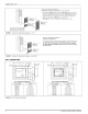
FIGURE
2:
Air
Distribution
Systems
Furnace
to
Closet
Door
Clearance
—
5
Inches
(12.7
cm)
or
more
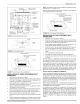
The
closet
door
MUST
have
a
minimum
of
250
Inches’(1613
cm’)
of
free
area
in
the
upper
half
of
the
door.
If
opening
for
return
air
is
located
in
the
floor
or
sidewalls and
below
the
top
of
the
furnace
casing:
Return
Air
Grille
Part
No.
7900-287P/A
*
White
7
1.
6
inches
(15.2
cm)
minimum
clearance
must
be
provided
on
side
250
IN?
(161
cm?)
where
return
is
located,
and
MINIMUM
2.
6
inches
(15.2
cm)
minimum
clearance
must
be
maintained
from
FREE
AREA
the
front
of
furnace.
250
IN2
(161
cm?)
; ;
MINIMUM
CLOSET
+
50
INS
(322
cm’)
FREE
AREA
FURNACE
}
mina
FREE
AREA
.
Pre
_
5
in
(12.7
cm)
or
greater
*
Closet
yeren
~
tae
™
to
Door
Clearance
Return
Air
Closet
Door
Part
No.
DOOR
7900-777
1/C*
White
FIGURE
3:
Closet
To
Door
Clearance
-
5”
or
Greater
Johnson
Controls
Unitary
Products
5