
Installation guide


129098-UIM-H-1011
TABLE
1:
Unit
Clearances
to
Combustibles
Top
Front
Rear
Sides
Roof
Jack
Flue
Floor
Duct!
Application]
Closet
|
Alcove
|
Closet
|
Alcove
|
Closet
|
Alcove
|
Closet
|
Alcove
|
Closet
|
Alcove
|
Closet
|
Alcove
|
Closet
|
Alcove
In.
(cm)
|
In.
(cm)
In.
(cm)
|
In.
(cm)
|
In.
(cm)|
In.
(cm)
|
In.
(cm)
]
In.
(cm)
|
In.
(cm)
|
In.
(cm)
|
In.
(cm)
In.
(cm)
|
In.
(cm)
|
In.
(cm)
Downflow
|
2(50.8)
|
2(50.8)
|6(15.24)|24(60.96)
0 0 0 0 0 0 0 0 0 0
.
Approved
duct
connector
required
for
use
on
combustible
floor.
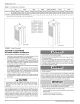
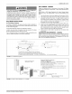
Inches
om.
A
|
59-1/2”
|
151.0
B
|
76"
193.0
C
|
24.3/4"
|
62.9
D
|
23"
58.4
E
|
19-1/2"
|
49.5
F
|
9-3/4”
24.8
G
|
12”
30.5
>
~
DGAH
Series
DGAA
Series
FIGURE
1:
Furnace
Dimensions
SECTION
II:
DUCTWORK
DUCTWORK
GENERAL
INFORMATION
The
duct
system’s
design
and
installation
must:
1.
2.
Handle
an
air
volume
appropriate
for
the
served
space
and
within
the
operating
parameters
of
the
furnace
specifications.
Be
installed
in
accordance
with
standards
of
NFPA
(National
Fire
Protection
Association)
as
outlined
in
NFPA
pamphlets
90A
and
90B
(latest
editions),
in
Canada
CAN/CGA-B149.1-00
Natural
Gas
and
Propane
Installation
Code.
or
applicable
national,
provincial,
or
state,
and
local
fire
and
safety
codes.
For
Manufacture
(Mobile)
Home
and
Modular
Home
Return
Duct
System
Installations:
The
return
air
duct
and
the
return
air
plenum
are
not
required
by
the
furnace
manufacturer,
provided
a
return
air
duct
and
plenum
are
not
required
by
state,
local,
or
regional
codes.
The
only
vent
system
that
is
approved
for
use
on
this
furnace
is
a
Roof
Jack
which
is
a
Sealed
Combustion
Direct
Vent
System.
Complete
a
path
for
heated
or
cooled
air
to
circulate
through
the
air
conditioning
and heating
equipment
and
to
and
from
the
condi-
A
CAUTION
The
cooling
coil
must
be
installed
in
the
supply
air
duct,
down-
stream
of
the
furnace.
Cooled
air
may
not
be
passed
over
the
heat
exchanger,
and
must
comply
with
(H.U.D.)
TITLE
24,
PART
3280.709
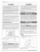
When
the
furnace
is
used
in
conjunction
with
a
cooling
coil,
the
coil
must
be
installed
parallel
with,
or
in
the
supply
air
side
of
the
furnace
to
avoid
condensation
in
the
primary
heat
exchanger.
When
a
parallel
flow
arrangement
is
used,
dampers
or
other
means
used
to
control airflow
must
be
adequate
to
prevent
chilled
air
from
entering
the
furnace.
If
manually
operated,
the
damper
must
be
equipped
with
means
to
pre-
vent
the
furnace
or
the
air
conditioner
from
operating
unless
the
damper
is
in
full
heat
or
cool
position.
The
duct
system
must
be
properly
sized
to
obtain
the
correct
airflow
for
the
furnace
size
that
is
being
installed.
Refer
to
the
furnace
rating
plate
for
the
correct
rise
range and
Table
4
for
static
pressures.
If
the
ducts
are
undersized,
the
result
will
be
high
duct
static
pres-
sures
and/or
high
temperature
rises
which
can
result
in
a
heat
exchanger
OVERHEATING
CONDITION.
This
condition
can
result
in
premature
heat
exchanger
failure,
which
can
result
in
personal
injury,
property
damage,
or
death.
HAZARD
OF
ASPHYXIATION,
DO
NOT
COVER
OR
RESTRICT
FLOOR
OPENING.
The
duct
system
is
a
very
important
part
of
the
installation.
If
the
duct
system
is
improperly
sized
the
furnace
will
not
operate
properly.
The
ducts
attached
to
the
furnace
plenum,
should
be
of
sufficient
size
so
that
the
furnace
operates
at
the
specified
external
static
pressure
and
within
the
air
temperature
rise
specified
on
the
nameplate.
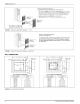
IMPORTANT
Fabricate
and
install
an
inspection
door
in
the
plenum
base
below
the
unit
to
allow
an
annual
inspection
of
the
heat
exchangers.
The
inspection
door
can
be
fabricated
by
the
following
method.
Cut
a
rectangular
opening
in
the
plenum
base.
A
sheet
metal
plate
can
be
made
that
completely
covers
the
open-
ing
in
the
base.
The
plate
must
be
secured
with
screws.
This
plate
must
be
sealed
to
prevent
leaks.
Johnson
Controls
Unitary
Products