
Installation guide


129098-UIM-H-1011
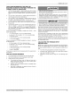
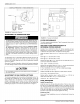
MANIFOLD
PRESSURE
“U”
TUBE
CONNECTION
(a
GAS
VALVE
t
3.5
IN
(0.87
kPa)
WATER
COLUMN
GAS
PRESSURE
SHOWN
FIGURE
30:
Reading
Gas
Pressure
ADJUSTMENT
OF
TEMPERATURE
RISE
ADANGER
The
temperature
rise,
or
temperature
difference
between
the
return
air
and
the
supply
(heated)
air
from
the
furnace,
must
be
within
the
range
shown
on the
furnace
rating
plate
and
within
the
application
limitations
shown
in
Table
7
“ELECTRICAL
AND
PERFORMANCE
DATA”.
The
supply
air
temperature
cannot
exceed
the
“Maximum
Supply
Air
Temperature”
specified
in
these
instructions
and
on
the
fur-
nace
rating
plate.
Under
NO
circumstances
can
the
furnace
be
allowed
to
operate
above
the
Maximum
Supply
Air
Temperature.
Operating
the
furnace
above
the
Maximum
Supply
Air
Temperature
will
cause
premature
heat
exchanger
failure,
high
levels
of
Carbon
Monoxide,
a
fire
hazard,
personal
injury,
property
damage,
and/or
death.
The
temperature
rise, or
temperature
difference
between
the
return
air
and
the
heated
supply
air
from
the
furnace,
must
be
within
the
range
shown
on
the
furnace
rating
plate
and
within
the
application
limitations
as
shown
in
Table
7.
After
about
20
minutes
of
operation,
determine
the
furnace
temperature
rise.
Take
readings
of
both
the
return
air
and
the
heated
air
in
the
ducts.
A
CAUTION
Do
not
energize
more
than
one
motor
speed
at
a
time
or
damage
to
the
motor
will
result.
ADJUSTMENT
OF
FAN
CONTROL
SETTINGS
This
furnace
is
equipped
with
a
time-on/time-off
heating
fan
control.
The
fan
off
delay
has
4
settings
(60,
90,
120
and
180
seconds).
The
fan
off
delay
is
factory
set
to
120
seconds.
The
fan-off
setting
must
be
long
enough
to
adequately
cool
the
furnace,
but not
so
long
that
cold
air
is
blown
into
the
heated
space.
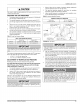
The
fan-off
timing
may
be
adjusted
by
positioning
the
jumper
on
two
of
the
four pins
as
shown
in
Figure
31.
TRANSFORMER
LINE
VOLTAGE
BLACK
-
HIGH
SPEED
RED
-LOW
SPEED
®
HL
HEAT
COOL
xFMR
NEUTRALS
FAN
OFF
JUMPER
FAN
ON
re
ADJUSTMENT]
JUMPER
I
SOOlE
0
OG]
>=
DOO]
3
FUSE
3A
®
rs!
FIGURE
31:
Furnace
Control
Board
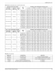
FILTER
PERFORMANCE
The
airflow
capacity
data
published
in
Table
9
represents
blower
perfor-
mance
WITHOUT
filters.
APPLYING
FILTER
PRESSURE
DROP
TO
DETERMINE
SYSTEM
AIRFLOW
Example:
For
a
90,000
BTUH
(26.4
kW)
furnace
operating
on
high-
speed
blower,
it
is
found
that
total
system
static
is
0.18”
(0.045 kPa)
w.c.
To
determine
the
system
airflow,
complete
the
following
steps:
Obtain
the
airflow
values
at
0.10
w.c.
(0.02
Pa)
&
0.20
w.c.
(0.05 Pa)
ESP.
Airflow
@
0.10":
1425
CFM
(40.4
m/min)
Airflow
@
0.20":
1380
CFM
(38.2
m/min)
Subtract
the
airflow
@
0.10
w.c.
(0.02 Pa)
from
the
airflow
@
0.20
w.c.
(0.05 Pa)
to
obtain
airflow
difference.
1425
-
1250
=
-175
CFM
(5.0
m/min)
Subtract
the
total
system
static
from
0.10
w.c.
(125
Pa)
and
divide
this
difference
by
the
difference
in
ESP
values
in
the
table
0.18
w.c.
(0.045
kPa)
-
0.10
w.c.
(125
Pa),
to
obtain
a
percentage.
(0.18
-
0.10)
/
(0.20
-0.10)=0.2
Multiply
percentage
by
airflow
difference
to
obtain
airflow
reduction.
(0.2)
X
(175)
=
-35
CFM
(0.99
m/min)
Subtract
airflow
reduction
value
to
airflow
@
0.10
w.c.
(125
Pa)
to
obtain
actual
airflow
@
0.18
in.
w.c.
(0.045
kPa)
ESP.
1425
(40.4)
-
35
=
1390
(39.4
m°/min)
FINAL
PROCEDURE
Install
Furnace
Doors
Install
the
lower
door
first
by
sliding
the
bottom
of
the
door
down
until
the
tabs
on
the
casing
base
engage
the
slots
in
the
bottom
door end
cap.
Then
push
the top
of
the
lower door
in
until
the
door
clips
snap
into
place.
Install
the
upper
door
in
a
similar
manner,
first
engaging
the
slots
in
the top
of
the
upper
door
on
the
tabs
on
the
casing
top.
Then
snap
the
bottom
of
the
upper
door
into
place
against
the
casing.
Finish
and
Trim
Alcove
and
Closet
Installations
may
now
be
finished
and
trimmed
as
necessary.
24
Johnson
Controls
Unitary
Products