
Installation guide


129098-UIM-H-1011
A
CAUTION
Be
sure
to
relight
any
gas
appliances
that
were
turned
off
at
the
Start
of
this
input
check.
CHECKING
THE
GAS
PRESSURES
1.
The
pressure
ports
on the
gas
valve
are
marked
OUT
PRESSURE
TAP
and
INLET
PRESSURE
TAP.
2.
The
manifoid
pressure must
be
taken
at
the
port
marked
OUT
P.
3.
The
inlet
gas
supply
pressure must
be
taken
at
the port
marked
IN
P.
4.
Using
a
3/32”
(0.2
cm)
Allen
wrench,
loosen
the
set
screw
by
turn-
ing
it
1
turn
counter
clockwise.
DO
NOT
REMOVE
THE
SET
SCREW
FROM
THE
PRESSURE
PORT.
5.
Push
one
end
of
the
3/8”
(0.9
cm)
ID
flexible
tubing
over
the
pres-
sure
port so that the
body
of
the port
is
inside
the
tubing.
6.
Use
a
reducer
connector
to
connect
the
3/8” (0.9
cm)
ID
flexible
tube
that
is
connected
to
a
“U”
tube
manometer
or
digital
pressure
measuring
equipment.
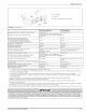
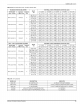
TABLE
7:
Inlet
Gas Pressure
Range
INLET
GAS
PRESSURE
RANGE
Natural
Gas
Propane
(LP)
Minimum
4.5"
W.C,
(1.12
kPa)
8.0”
W.C.
(1.99
kPa)
Maximum
10.5”
W.C,
(2.61
kPa)
13.0”
(3.24
kPa)
W.C.
IMPORTANT
The
inlet
gas
pressure
operating
range
table
specifies
the
minimum
and
maximum
gas
line
pressures
required
for
safe
furnace
opera-
tion.
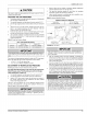
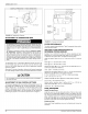
1.
Refer
to
Figure
29
for
location
of
pressure
regulator
adjustment
cap
and
adjusiment
screw
on
main
gas
vaive.
2.
Turn
gas
and
electrical
supplies
on
and
follow
the
operating
instructions
to
place
the
unit
back
in
operation.
3.
Adjust
manifold
pressure
by
adjusting
gas
valve
regulator
screw
for
the
appropriate
gas
per
the
following:
TABLE
8:
Nominal
Manifold
Pressure
NOMINAL
MANIFOLD
PRESSURE
Natural
Gas
3.5”
w.c.
(0.87
kPa)
Propane
(LP)
Gas
10.0"
w.c.
(2.488
kPa)
OUTLET
(MANIFOLD)
MAIN
REGULATOR
PRESSURE
TAP
/
[.
ADJUSTMENT
a
a
90°
INLET
(7
©)
<
SUPPLY
=
Qe
PRESSURE—*
TAP
2
ww
|
OS
ELECTRICAL
ON/OFF
SWITCH
CONNECTIONS
(shown
in
OFF
position)
OUTLET
FIGURE
29:
Gas
Valve
IMPORTANT
If
gas
valve
regulator
is
turned
in
(clockwise),
manifold
pressure
is
increased.
If
screw
is
turned
out
(counter
clockwise),
manifold
pres-
sure
will
decrease.
The
minimum
inlet
gas
pressure
required
to
obtain
the
BTU
input
speci-
fied
on
the
rating
plate
and
in
these
instructions
is
shown
below:
«
45°
W.C.
(1.12
KPA)
for
Natural
Gas
«
11.0”
W.C.
(2.74
KPA)
for
Propane
(LP)
Gas
ADJUSTMENT
OF
MANIFOLD
GAS
PRESSURE
Manifold
gas
pressure
may
be
measured
at
the
gas
valve.
Turn
gas
off
at
the
ball
valve
or
gas
cock
on
gas
supply
line
before
the
gas
valve.
Find
the
pressure
ports
on
the
gas
valve
marked
OUT
P
and
IN
P.
1.
The
manifold
pressure must
be
taken
at
the
port
marked
OUT
P.
2.
The
gas
line
pressure must
be
taken
at
the
port
marked
IN
P.
3.
Using
a
3/32”
Allen
wrench,
loosen
the
set
screw
by
turning
it
1
turn
counter
clockwise.
DO
NOT
REMOVE
THE
SET
SCREW
FROM
THE
PRESSURE
PORT.
Use
the
4”
(10.2
cm)
piece
of
1/8”
(0.3
cm)
tubing
to
connect
the
posi-
tive
side
of
the
manometer
to
the
gas
valve
pressure
reference
port.
Refer
to
Figure
30
for
connection
details.
IMPORTANT
The
cap
for
the
pressure
regulator
must
be
removed
entirely
to
gain
access
to
the
adjustment
screw.
Loosening
or
tightening
the
cap
does
not
adjust
the
flow
of
gas.
4.
After
the
manifold
pressure
has
been
adjusted,
re-calculate
the
furnace
input
to
make
sure
you
have
not
exceeded
the
specified
input
on the
rating
plate.
Refer
to
“CALCULATING
THE
FURNACE
INPUT
(NATURAL
GAS)’.
5.
Once
the
correct
BTU
(kW)
input
has
been
established,
turn
the
gas
valve
to
OFF
and
turn
the
electrical
supply
switch
to
OFF;
then
remove
the
flexible
tubing
and
fittings
from
the
gas
valve
pressure
tap
and
tighten
the
pressure
tap
plug
using
the
3/32” Allen
wrench.
6.
Turn
the
electrical
and
gas
supplies
back
on,
and
with
the
burners
in
operation,
check
for
gas
leakage
around
the
gas
valve
pressure
port
for
leakage
using
an
approved
gas
detector,
a
non-corrosive
leak
detection
fluid,
or
other
leak
detection
methods.
The
manifold
pressure
must
be
checked
with the
screw-off
cap
for
the
gas
valve
pressure
regulator
in
place.
If
not,
the
manifold
pres-
sure
setting
could
result
in
an
over-fire
condition.
A
high
manifold
pressure
will
cause
an
over-fire
condition,
which
could
cause
pre-
mature
heat
exchanger
failure.
If
the
manifold
pressure
is
too
low,
sooting
and
eventual
clogging
of
the
heat
exchanger
could
occur.
Be
sure
that
gas
valve
regulator
cap
is in
place
and
burner
box
to
gas
valve
pressure
reference
hose
is
connected.
Johnson
Controls
Unitary
Products
23