
Installation guide


129098-UIM-H-1011
CARBON
MONOXIDE
POISONING
HAZARD
Failure
to
follow
the
steps
outlined
below
for
each
appliance
connected
to
the
venting
system
being
placed
into
operation
could
result
in
carbon
monoxide
poisoning
or
death.
The
following
steps
shall
be
followed
for
each
appliance
connected
to
the
venting
system
being
placed
into
operation,
while
ail
other
appliances
connected
to
the
venting
system
are
not
in
operation:
1.
Inspect
the
venting
system
for
proper
size
and
horizontal
pitch.
Determine
that
there
is
no
blockage,
restriction,
leakage,
corrosion
or
other
deficiencies,
which
could
cause
an
unsafe
condition
2.
Close
all
building
doors
and
windows
and
ail
doors.
3.
Turn
on
clothes
dryers
and
TURN
ON
any
exhaust
fans,
such
as
range
hoods
and
bathroom
exhausts,
so
they
shail
operate
at
maximum
speed.
Open
the
fireplace
dampers.
Do
not
operate
a
summer
exhaust
fan.
4.
Follow
the
lighting
instructions.
Place
the
appliance
being
inspected
in
operation.
Adjust
thermostat
so the
appliance
shall
operate
contin-
uously.
5.
Test
each
appliance
(such
as
a
water
heater)
equipped
with
a
draft
hood
for
spillage
(down-draft
or
no
draft)
at
the
draft
hood
relief
opening
after
5
minutes
of
main
burner
operation.
Appliances
that
do
not
have
draft
hoods
need
to
be
checked
at
the
vent
pipe
as
close
to
the
appliance
as
possible.
Use
a
combustion
analyzer
to
check
the
CO2
and
CO
levels
of
each
appliance.
Use
a
draft
gauge
to
check
for
a
downdraft
or
inadequate
draft
condition.
6.
After
it
has
been
determined
that
each
appliance
properly
vents
when
tested
as
outlined
above,
return
doors,
windows,
exhaust
fans,
fire-
place
dampers
and any
other
gas
burning
appliance
to
their
normal
condition.
7.
\f
improper
venting
is
observed
during
any
of
the
above
tests,
a
problem
exists
with
either
the
venting
system
or
the
appliance
does
not
have
enough
combustion
air
(Supply
Air
from
outside)
to
complete
combustion.
This
condition
must
be
corrected
before
the
appliance
can
function
safely.
NOTE:
An
unsafe
condition
exists
when
the
CO
reading
at
the
furnace
vent
exceeds
40
ppm
and
the
draft
reading
is
not
in
excess
of
-
0.1
in.
W.C.
(-25
kPa)
with
all
of
the
appliance(s)
operating
at
the
same
time.
8.
Any
corrections
to
the
venting
system
and
/
or
to
the
supply
(outside)
air
system
must
be
in
accordance
with
the
National
Fuel
Gas
Code
2223.1
or
CAN/CGA
B149.1-00
Natural
Gas
and
Propane
Installation
Code
(latest
editions).
If
the
vent
system
must
be
resized,
follow
the
appropriate
tables
in
Appendix
G
of
the
above
codes
or
for
this
appliance.
FAN-ASSISTED
COMBUSTION
SYSTEM
An
appliance
equipped
with
an
integral
mechanical
means
to
either
draw
or
force
products
of
combustion
through
the
combustion
chamber
and/or
heat
exchanger.
SECTION
VIII:
SAFETY
CONTROLS
CONTROL
CIRCUIT
FUSE
A
3-amp
fuse
is
provided
on the
control
circuit
board
to
protect
the
24-
volt
transformer
from
overload
caused
by
control
circuit
wiring
errors.
This
is
an
ATO
3,
automotive
type
fuse
and
is
located
on the
control
board.
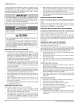
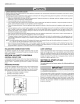
PRESSURE
SWITCHES
This
furnace
is
supplied
with
a
pressure
switch,
which
monitors
the
flow
through
the
combustion
air/vent piping
system.
This
switch
de-ener-
gizes
the
ignition
control
module
and
the
gas
valve
if
any
of
the
follow-
ing
conditions
are
present.
Refer
to
Figure
28
for
tubing
connections.
1.
Blockage
of
combustion
air
piping
or
terminal.
2.
Blockage
of
vent
piping
or
terminal.
3.
Failure
of
combustion
air
blower
motor.
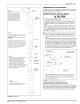
FIGURE
28:
Pressure
Switch
Tubing
Routing
LIMIT
CONTROLS
There
is
high
temperature
limit
control
located
on
the
furnace
vestibule
panel
near
the
gas
valve.
This
is
an
automatic
reset
control
that
pro-
vides
over
temperature
protection
due
to
reduced
airflow, that
may
be
caused
by
a
dirty
filter,
or
if
the
indoor
fan
motor
should
fail.
The
control
module
will
lockout
if
the
limit
trips
3
consecutive
times.
Control
will
reset
and
try
ignition
again
after
1
hour.
SECTION
IX:
START-UP
AND
ADJUSTMENTS
The
initial
start-up
of
the
furnace
requires
the
following
additional
procedures:
IMPORTANT
All
electrical
connections
made
in
the
field
and
in
the
factory
should
be
checked
for
proper
tightness.
When
the
gas
supply
is
initially
connected
to
the
furnace,
the
gas
piping
may
be
full
of
air.
In
order
to
purge
this
air,
it
is
recommended
that
the
ground
union
be
loosened
until
the
odor
of
gas
is
detected.
When
gas
is
detected,
immediately
retighten
the
union
and
check
for
leaks.
Allow
five
minutes
for
any gas
to
dissipate
before
continuing
with
the
start-up
procedure.
Be
sure
proper
ventilation
is
available
to
dilute
and
carry
away
any
vented
gas.
20
Johnson
Controls
Unitary
Products