
Installation guide


129098-UIM-H-1011
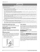
COMBUSTION
AIR
PIPE
AND
FLUE
ASSEMBLY
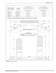
THIS
JOINT
MUST
BE
BELOW
CEILING
INTERIOR
EXTENSION
(OPTIONAL)
FURNACE
COMBUSTION
AIR
COLLAR
A
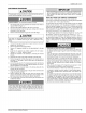
CAUTION
Use
1/2”
(1.27
cm)
blunt
or
sharp
end
sheet
metal
screws
to
fasten
roof
jack
combustion
air
pipe
to
furnace
combustion
air
collar
Screw
holes
are
provided
in
pipe
and
collar.
Excessively
long
screws
may
extend
to
flue
pipe
and
puncture
it.
If
substitute
screws
are
used,
they
must
not
exceed
7
1/2”
(3.81
cm)
in
length.
It
is
mandatory
that
the
combustion
air
and
flue
tube
assembly
be
properly
engaged,
and
the
combustion
air
pipe
fastened
to
the
furnace
with
sheet
metal
screws
in
the
holes
provided.
FIGURE
25:
Roof
Jack
Assembly
INTERIOR
EXTENSIONS
To
choose
the
proper
length
roof
jack
with
or
without
the
optional
exten-
sion
see
Figure
25
and
Table
8.
More
than
one
interior
extension
may
be
used
to
accommodate
A
“dimensions
up
to
110”
(284.5
cm).
AWARNING
The
joint
where
the
optional
interior
extension
connects
to
the
roof
jack
must
be
below
the
ceiling.
Failure
to
observe
this
requirement
may
result
in
asphyxiation,
fire,
or
explosion
NOTE:
Use
of
an
interior
extension
will
increase
the
roof
jack
adjust-
able
heights
by the
amount
of
the
interior
extension
height.
If
the
fur-
nace
is
installed
on
an
elevated
plenum,
the
plenum
height
must
be
added
to
the roof
jack
height.
A
CAUTION
Do
not
exceed
the
maximum
adjustable
height
as
listed
in
Table
6.
These
maximum
heights
allow
an
additional
1
1/2”
(3.817
cm)
travel
before
the
flue
pipe
assembly
is
fully
extended
against
the
built-in
stop.
This
provides
an
additional
safeguard
against
the
flue
assem-
bly
being
pulled
from
the
roof
jack
if
upward
movement
should
occur
when
the
home
is
being
transported
or
subjected
to
other
stress
conditions.
Failure
to
follow
these
instructions
may
result
in
fire,
explosion,
or
asphyxiation.
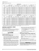
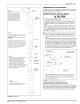
TABLE
6:
Roof
Jack
Options
Roof
Jack
|
Adjustable
Height
with
|
Adjustable
Height
with
Model
Number]
no
Interior
Extension
|
on
17”
Interior
Extension
4000B7141
14”
to
78”
64”
to
95”
4000B7151
66”
to
90”
83”
to
107”
4000B8161
59”
to
79” 76”
to
96”
4000B8181
73”
to
103”
90”
to
110”
Models
4000B8161
and
4000B8181
have
removable
crowns.
If
using
an
optional
interior
extension,
place
extension
down
on
furnace
top
and
mate
with
furnace
flue
and
combustion
air
collar
until
it
lines
up
with
screw
holes
in
combustion
air
collar.
Secure
the
extension
to
the
furnace
using
the
pre-punched
holes.
Use
1/2”
(1.27
cm)
blunt
or
sharp
end
sheet
metal
screws
to
fasten
roof
jack
combustion
air
pipe
to
fur-
nace
combustion
air
collar.
Screw
holes
are
provided
in
pipe
and
collar.
Excessively
long
screws
may
extend
to
flue
pipe
and
puncture.
it.
if
substitute
screws
are
used.
they
must
not
exceed
1
1/2”
(3.8a
cm)
in
length.
Pull
the
roof
jack
flue
and
combustion
air
pipe
assembly
down
and
mate
with
extension
flue
and
combustion
air
pipes
until
the
screw
holes
line
up.
See
Figure
25.
Fasten
interior
extension
to
combustion
air
pipe
assembly
with
sheet
metal
screws
not
exceeding
1
1/2”
(3.8
cm)
in
length.
IMPORTANT
Under
no
circumstances
shail
the
connection
between
the
flue
and
combustion
air
pipe
assembly
of
the
roof
jack
and
the
interior
exten-
sion
be
above
the
ceiling
line.
Secure
the
roof
jack
to
the
roof with
screws.
Non-hardening
mastic
sealer
or
caulking
compound
must
be
used
to
seal
the
roof
flange
to
prevent
water
leakage.
The
roof
jack
swivel
joint
must
also
be
sealed
to
prevent
water
leakage.
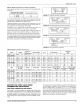
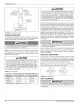
INSTALLING
CEILING
RING
The
ceiling
ring
is
to
meet
fire
stop
requirements.
Accessory
Ceiling
Ring
may
be
used (See
Figure
26)
or
the
mobile
home
or
modular
home
manufacturer
or
the
installer
may
use
other
approved
methods
to
fire
stop.
If
required,
three
sections
of
the
Accessory
ring
may
be
used
as
in
Figure
26
to
provide
closer
clearance
around
the
roof
jack.
NOTE:
A
portion
of
the
outer
edge
of
the
ceiling
ring
may
be
trimmed
so
the
ring
will
fit
between
the
warm
air
plenum
and
roof
jack.
DO
|
>
D
?
FIGURE
26:
Ceiling
Rings
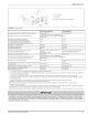
VENT
CLEARANCES
IMPORTANT
The
vent
must
be
installed
with the
minimum
clearances
as
shown
in
Figure
27,
and
must
comply
with
local,
state,
regional
codes
and
requirements.
18
Johnson
Controls
Unitary
Products