
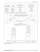
Installation guide

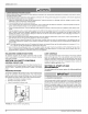

STEP
1:
Remove
upper
and
lower
cap.
Remove
the
two
(2)
screws
that
secure
the
upper
cap
to
the
crown
assembly
base
and
remove
the
upper
cap.
Next,
er
remove
the
three
(3)
screws
=|
fe
CROWN
that
secure
the
lower
cap
to
YL
prep
the
crown
assembly
base.
Set
bothcaps
aside
for
later
use.
ae
Ce
STEP
2:
bet
Place
the
roof
jack
extension
on
top
of
the
crown
assembly
base,
pushing
down
firmly
fo
assure
a
snug
fit.
IMPORTANT:
Make
sure
that
the
pipes
are
connected,
—
Extensi
Using
the
four
(4)
holes
at
the
base
of
the
HENSON
extension
as
a
guide,
drill
four
(4)
holes
eo
Pane
1/8”
diarneter
into
the
crown
assembly
base.
’
Secure
the
extension
to
the
crown
assembly
base
with
the
four
(4)
screws
provided.
Install
the
lower
cap
on
top
of
the
extension
so
that
the
center
pipe
sticks
through
the
hole
in
the
lower
cap.
Crown
Assembly
Base
_.
UPPER
CAP
STEP
3:
Reinstall
upper
and
lower
cap
to
extension.
—
LOWER
Using
the
three
(3)
screws
removed
CAP
in
Step
1,
attach
the
lower
cap
to
the
extension
bracket.
Install
the
upper
_
EXTENSION
cap
over
the
center
pipe
of
the
extension.
BRACKET
Using
the
two
(2)
holes
located
at
the
base
of
the
upper
cap
as
guides,
drill
F——
EXTENSION
two
(2)
1/8”
diameter
holes
into
the
center
pipe.
Finally,
attach
the
upper
cap
to
the
center
pipe
using
the
two
(2)
screws
removed
in
Step
1
to
the
center
pipe.
CROWN
ASSEMBLY
BASE
STEP
4:
Complete
assembly.
Place
these
instructions
in
the
customer
packet
provided
with
the
furnace.
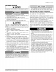
FIGURE
23:
Roof
Jack
129098-UIM-H-1011
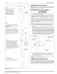
EXTERIOR
ROOF
JACK
EXTENSION
Available
to
comply
with
instances
in
which
the
roof
jack
crown
needs
to
be
raised
to
meet
a
roof
clearance
requirement.
One
extension
will
raise
the
roof
jack
crown
by
18
inches.
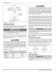
CONNECTING
ROOF
JACK
TO
FURNACE
A
CAUTION
The
inner
flue
pipe
must
be
present.
It
is
mandatory
that
the
combustion
air
pipe
and
flue
pipe
assem-
bly
be
fully
engaged.
The
combustion
air
pipe
MUST
be
securely
fastened
to
the
furnace
with
a
sheet
metal
screw
in
the
hole
pro-
vided.
Use
a
1/2"
blunt
or
sharp
end
sheet
metal
screw
to
fasten
roof
jack
combustion
air
pipe
to
furnace
combustion
air
collar.
Screw
hole
is
provided
in
the
pipe
and
collar.
Excessively
long
screws
may
extend
to
flue
pipe
and
puncture
it.
Screws
are
not
to
exceed
7
1/2”
in
length.
NOTE:
Combustion
air
tube
and
flue
pipe
are
part
of
the
same
assem-
bly.
Only
the
combustion
air
tube
need
be
fastened
to
the
furnace.
1.
Check
to
be
certain
that the
flue
pipe
and
combustion
air
tube
are
present.
2.
Pull
the
telescoping
flue
tube
and
combustion
air
tube
assembly
down
from
the
roof
jack.
Slide
the
flue
tube/combustion
air
tube
assembly
down
firmly
over
the
furnace
flue
outlet
and
combustion
air
collar.
Insure
that
the
back,
side
and
front
of
combustion
air
tube
collar
is
fully
engaged
and
is in
contact
with
gasket.
Fasten
the
combustion
air
tube
to
the
furnace
combustion
air
collar
using
a
1/2
inch
sheet
metal
screw.
(Screw
hole
provided
in
combustion
air
tube
and
furnace
combustion
air
collar.
See
Figure
24).
COMBUSTION
AIR
TUBE
|
SECURE
STRAP
TO
WALL
\
#8
OR
#10
SCREW
RECOMMENDED
COMBUSTION
AIR
TUBE
COLLAR
FURNACE
—K
c=
LUE
OUTLET
FRONT
OF
FURNACE
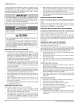
It
is
mandatory
that
the
combustion
air
and
flue
tube
assembly
be
fully
engaged
at
back
sides
and
front,
and
combustion
air
tube
securely
fastened
to
the
furnace
with
a
sheet
metal
screw
in
the
screw
hole
provided.
FIGURE
24:
Connecting
Roof
Jack
to
Furnace
COMBUSTION
AND
VENTILATION
AIR
This
furnace
is
a
sealed
combustion
(direct
vent)
unit
and
is
design
cer-
tified
to
use
only
a
4000
Series
roof
jack.
These
roof
jacks
are
designed
to
provide
combustion
air
to
the
furnace
and
to
exhaust
flue
products
to
the
outside.
No
other
combustion
air
openings
or
ducts
are
needed.
Johnson
Controls
Unitary
Products
17