
Installation guide


129098-UIM-H-1011
Eighteen
gauge
thermostat
wire
is
highly
recommended.
Smaller
gauge
thermostat
wire
may
be
used
only
if
the
guideline
below
is
followed.
Thermostat
Wire
Length
(Furnace
to
Thermostat)
0
-
45
feet
22
0
-
70
feet
20
Thermostat
Wire
Gauge
Do
not
use
the
thermostat
wire
smaller
than
22
gauge.
if
thermostat
wire
small
than
18
gauge
is
used,
pay
particular
attention
that
the
con-
nections
between
the
different
wire
sizes
are
tight.
Operational
problems
may
be
caused
by
loose
connections
or
by
the
use
of
thermostat
wire
that
is
too
small
to
carry
the
required
load.
Any
such
problems
are
the
responsibility
of
the
installer.
A
separate
115
V.A.C.
supply
circuit
must
be
used
for
the
furnace.
The
circuit
should
be
protected
by
a
15
amp
fuse
or
circuit
breaker.
Avoid
locations
where
the
thermostat
could
be
subject
to
drafts
from
outside,
or
exposed
to
direct
light
from
lamps,
sun,
fireplaces,
etc.,
or
affected
by
air
from
a
duct
register
blowing
directly
on the
thermostat.
The
wall
thermostat
should
be
located
52
to
66
inches
above
the
floor.
The
preferred
location
is
on an
inside
wall
situated
in
an
area
with
good
air
circulation,
and
where
the
temperature
will
be
reasonably
represen-
tative
of
other
living
areas
the
thermostat
is
controlling.
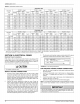
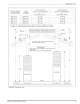
TABLE
5:
Ratings
&
Physical
/
Electrical
Data
Nominal
CFM(m?/min)
cmm
n.
cm
Input
Output
Cabinet
Width
Max.
Outlet
Air
Temp
Blower
Size
Blower
p
n.
em
x
x
1.
0.3”
Ext.
Static
Duct
Pressure
-
No
Coil
-
Std.
Blower
-
High
Speed
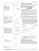
SECTION
VII:
ROOF
JACK
VENT/
COMBUSTION
AIR
SYSTEM
VENT
AND
COMBUSTION
AIR
SAFETY
This
Category
|,
furnace
is
designed
for
Manufactured
(Mobile)
Home
and
Modular
Home
application.
It
may
be
installed
without
modification
in
a
garage,
equipment
room,
alcove
or
any
other
indoor
location
where
all
required
clearance
to
combustibles
and
other
restrictions
are
met,
AND
providing
factory
Roof
Jack
System
meets
ail
installation
require-
ments.
Total
Unit
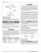
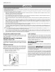
ROOM
FURNACE
THERMOSTAT
CONTROL
RETR
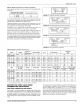
FIGURE
17:
Wiring
for
Heat
Only
Thermostat
ROOM
FURNACE
CONDENSING
THERMOSTAT
CONTROL
UNIT
2
nn
R |
TO
AIR
CONDITIONER
w
w
CONTROLS
[S|
a
Y¥.
ca
m
c
wots
COMMON
T’STAT
CONNECTION
FIGURE
18:
Wiring
for
Electronic
Heat-Cool
Thermostat
ROOM
FURNACE
CONDENSING
THERMOSTAT
PIGTAILS
UNIT
R
[R]
TO
AIR
CONDITIONER
=
pw
CONTROLS
|S]
aR
¥
a
te
:
FIGURE
19:
Wiring
for
Standard
Heat-Cool
Thermostat
ROOM
FURNACE
CONDENSING
THERMOSTAT
PIGTAILS
UNIT
R
iR
|
TO
AIR
CONDITIONER
ww
jw
CONTROLS
|
Re
*
———a-
—
{
i
BLEND
AIR
CONTROL
BOX
FIGURE
20:
Wiring
for
Blend
Air
Accessory
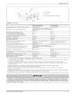
Operation
Air
Temp.
Rise
Wot.
Min.
wire
Size
Over-Current
|
(awg)
@
75
ft
Protect
one
way
Booster
Motor
Max
ignitor
&
Gas
Valve
ps ps
The
venting
system
must
be
installed
in
accordance
with
Section
5.3,Air
for
Combustion
and
Ventilation,
of
the
National
Fuel
Gas
CodeZ223.1/
NFPA
54
(latest
edition),
or
Sections
7.2,
7.3
or
7.4
of
CAN/CGA
B149.1-00,
National
Gas
and
Propane
Codes
(latest
edition)
or
applica-
ble
provisions
of
the
local
building
code
and
these
instructions.
The
fur-
nace
shall
not
be
connected
to
any
chimney,
a
flue
serving
a
separate
appliance,
or
any
appliance
designed
to
burn
solid
fuel.
The
furnace
rat-
ing
plate
lists
the
maximum
vent
gas
temperature.
Johnson
Controls
Unitary
Products
13