
Installation guide


129098-UIM-H-1011
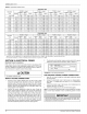
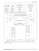
TABLE
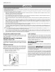
4:
High
Altitude
Duration
Chart
NATURAL
GAS
.
56,000
—
Input
70,000
—
Input
77,000
—
Input
90,000
—
Input
Elevation
Orifice
|
Drill
Orifice
|
Drill
Orifice
|
Drill
Orifice
|
Drill
Feet
Meters)
“bia
|
size
|
Pat*
|
pia
|
size
|
P@t*
|
pia
|
size
|
PAt*
|
dia
|
size
|
Patt
Sea
Level
0.136
|
29
|9051-1361|
0.154
|
23
19051-1541]
0.161
|
20
|
9951-1611]
0.180
|
15
19951-1801
2,000
618
|
0.136
|
20
|
9951-1361]
0.149
|
25
19051-1401]
0.157
|
22
19951-1571]
0.177
|
16
|
9051-1771
3,000
974
|
0.128
|
30
|
9951-1281]
0.149
|
25
19051-1491]
0.157
|
22
|9951-1571|
0.173
|
147
|
9951-1731
4,000
7219
|
0.128
|
30
|9051-1281|
0147
|
26
|
9051-1471]
0.154
|
23
9051-1541]
0.173
|
17
19951-1731
5000
7524
|
0.128
|
30
|9051-1281|
0.144
|
27
[9051-1441]
0.152
|
24
|
9051-1521]
0.169
|
18
19951-1601
6,000
7829
|
0.128
|
30
|9051-1281|
0.144
|
27
[9951-1441]
0.149
|
25
|
9951-1491]
0.166
|
19
19951-1661
7,000
3134
|
0.120
|
31
19951-1201]
0.140
|
28
19951-14011
0.147
|
26
|
9951-1471|
0.161
|
20
|
9957-1611
8,000
2438
|
0.120
|
31
|
9951-1201}
0.136
|
29
|9951-1361|
0.144
|
27
|9051-1447|
0.161
|
20
|
9957-1611
9,000
2743
|
0.120
|
31
19951-1201]
0.136
|
29
[9951-13611
0.140
|
28
|
9951-1401]
0.157
|
22
|
9051-1571
70,000
3048
|
0.116
|
32
|
9951-1161]
0.128
|
30
|
9051-1281|
0136
|
29
|9051-1361|
0.152
|
24
|
9051-1521
PROPANE
GAS
Elevation
a
-
ee
=<
—
Input
=<
a
Input
<a
—
Input
riice
fl
ririce
fl
riice
fl
rice
fl
Feet
Meters)
“bia
|
size
|
Pat*
|
pia
|
size
|
P@t*
|
pia
|
size
|
PAt*
|
dia
|
size
|
Patt
Sea
Level
0.082
|
45
|9051-0821|
0.093
|
42
|
9051-0931]
0.098
|
40
|
9951-0981]
0.106
|
36
19951-1061
2,000
618
|
0.081
|
46
|
9951-0811
|
0.093
|
42
19051-0931]
0.096
|
41
|
9951-0961]
0.104
|
37
|
9051-1041
3,000
974
|
0.078
|
47
|
9951-0781]
0.089
|
43
[9951-0891]
0.093
|
42
|9951-0931|
0.101
|
38
[9957-1011
4,000
7219
|
0.078
|
47
|9951-0781|
0.089
|
43
[9951-0891]
0.093
|
42
[9951-0931]
0.101
|
38
|
9051-1011
5,000
1524
|
0.078
|
47
|
9051-0781|
0.089
|
43
|
9951-0801]
0.093
|
42
|
9951-0931}
0.099
|
39
19951-0901
6,000
7829
|
0.076
|
48
|9051-0761|
0.086
|
44
|
90951-0861]
0.089
|
43
|
9951-0891]
0.098
|
40
19951-0981
7,000
2134
|
0.076
|
48
|
9951-0761]
0.086
|
44
[9951-08611
0.089
|
43
|9951-0801|
0.096
|
41
|
9951-0901
8,000
3438
|
0.073
|
49
|
9951-0731]
0.082
|
45
19951-08211
0.086
|
44
|
9051-0861|
0.096
|
41
|
9051-0901
9,000
2743
|
0.073
|
49
|
9951-0731]
0.081
|
46
|
9951-08111
0.086
|
44
|9951-0861|
0.093
|
42
|
9051-0931
70,000
3048
|
0.070
|
50
19951-0700]
0.078
|
47
|9951-0781|
0.082
|
45
|9051-0821|
0.089
|
43
|
9951-0801
Table
shows
4%
Input
Reduction
per
1,000
feet
Elevation.
Reference
Source:
NFPA
No.
54,
ANSI
Z
223.1,
National
Fuel
Gas
Code.
For
Canadian
installation,
no
orifice
or
manifold
pressure
reduction
is
required
for
0-4,
500ft.
SECTION
VI:
ELECTRICAL
POWER
Electrical
Power
Connections
Field
wiring
to
the
unit
must
be
grounded.
Electric
wires
that
are
field
installed
shall
conform
to
the
temperature
limitation
for
63°F
(35°C)
rise
wire
when
installed
in
accordance
with
instructions.
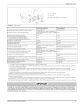
Refer
to
Table
5
in
these
instructions
for
specific
furnace
electrical
data.
A
CAUTION
Use
copper
conductors
only.
SUPPLY
VOLTAGE
CONNECTIONS
1.
Provide
a
power
supply
separate
from
all
other
circuits.
Install
overcurrent
protection
and
disconnect
switch
per
local/national
electrical
codes.
The
switch
should
be
close
to
the
unit
for
conve-
nience
in
servicing.
With
the
disconnect
or
fused
switch
in
the
OFF
position,
check
all
wiring
against
the
unit
wiring
label.
Refer
to
the
wiring
diagram
in
this
instruction.
2.
Remove
the
screws
retaining
the
wiring
box
cover.
Route
the
power
wiring
through
the
opening
in
the
unit
into
the
junction
box
with
a
conduit
connector
or
other
proper
connection.
In
the
junction
box
there
will
be
three
wires,
a
Black
Wire,
a
White
Wire
and
a
Green
Wire.
Connect
the
power
supply
as
shown
on
the
unit-wir-
ing
label on
the
inside
of
the
blower
compartment
door
or
the
wir-
ing
schematic
in
this
section.
The
black
furnace
lead
must
be
connected
to
the
L1
(hot)
wire
from
the
power
supply.
The
white
furnace
lead
must
be
connected
to
neutral.
Connect
the
green
fur-
nace
lead
(equipment
ground)
to
the
power
supply
ground.
3.
The
furnace's
control
system
requires
correct
polarity
of
the
power
supply
and
a
proper
ground
connection.
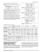
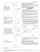
Refer
to
Figure
16.
BLK
___m
BLK
(HOT)
no
NOMINAL
WHT
__@
WHT
(NEUTRAL)
420
VOLT
GRN__m
GRN
a
FIGURE
16:
Line
Wiring
Connections
LOW
VOLTAGE
CONTROL
WIRING
CONNECTIONS
1.
2.
4.
Insert
24
volt
wires
through
the
small
plastic
bushing
just
above
the
control
panel.
Connect
the
thermostat
wires
to
the
furnace
low
voltage
pigtails.
See
Figure
17
(heating
only)
and
Figure
18
or
19
(heating
and
cooling).
Connect
thermostat
wires
to
the
furnace
when
installing
blend
air
accessory
as
shown
in
Figure
20.
Connect
low-voltage
circuit
to
the wail
thermostat
pigtails.
NOTE:
Five-conductor
thermostat
cable
is
recommended
for
ail
instal-
lations
to
allow
easy
installation
of
an
air
conditioning
system
at
a
later
time.
IMPORTANT
Set
the
heat
anticipator
in
the
room
thermostat
to
0.40
amps.
Set-
ting
it
lower
will
cause
short
cycles.
Setting
it
higher
will
cause
room
temperature
to
exceed
the
set
points.
12
Johnson
Controls
Unitary
Products