
Installation guide


129098-UIM-H-1011
A
CAUTION
To
install
gas
line
and
to
connect
it
to
the
gas
valve,
care
must
be
taken
to
hold
gas
vaive
firmly
to
prevent
misalignment
of
the
burner
orifice,
or
to
damage
gas
valve
which
could
result
in
improper
heat-
ing,
explosion,
fire
or
asphyxiation.
DO
NOT
USE
EXCESSIVE
PIPE
SEALANT
ON
PIPE
JOINTS.
Pipe
sealant,
metal
chips
or
other
foreign
material
that
could
be
deposited
in
the
inlet
of
the
gas
valve,
when
gas
pipe
is
installed
or
carried
through
the
gas
piping
into
the
gas
valve
inlet
after
installa-
tion,
may
cause
the
gas
valve
to
malfunction and
could
result
in
possible
improper
heating,
explosion,
fire
or
asphyxiation.
Also,
pipe
sealant
must
be
resistant
to
Propane
gas.
Where
regulations
require,
a
main
shut-off
valve
shall
be
installed
externally
of
furnace
casing.
After
piping
has
been
installed,
turn
gas
on
and
check
all
connections
with
a
leak
detector
or
soap
solu-
tion.
Never
use
open
flame
to
test
for
gas
leaks
as
fire
or
explosion
could
occur.
Do
not
test
the
fuel
system
at
more
than
14”
W.C.
after
furnace
has
been
connected
to
fuel
line.
Such
testing
could
void
the
warranty.
Any
test
run
above
14”
WC.
may
damage
furnace
control
valve
which
could
cause
an
explosion,
fire
or
asphyxiation.
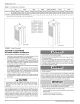
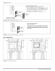
A
drip
leg
is
recommended
in
the
gas
supply
line
to
trap
moisture
and
contaminations.
Refer
to
Figure
14.
For
natural
gas
operation,
the
furnace
is
designed
for
7"
W.C.
inlet
gas
pressure.
Pressure
to
main
burner
is
then
reduced
to
3
1/2"
W.C.
GAS
PIPING
INSTALLATION
Properly
sized
wrought
iron,
approved
flexible
or
steel
pipe
must
be
used
when
making
gas
connections
to
the
unit.
if
local
codes
allow
the
use
of
a
flexible
gas
appliance
connection,
always
use
a
new
listed
con-
nector.
Do
not
use
a
connector
that
has
previously
serviced
another
gas
appliance.
Some
utility
companies
or
local
codes
require
pipe
sizes
larger
than
the
minimum
sizes
listed
in
these
instructions
and
in
the
codes.
The
furnace
rating
plate
and
the
instructions
in
this
section specify
the
type
of
gas
approved
for
this
furnace
-
only
use
those
approved
gases.
¢—
MANUAL
SHUT-OFF
VALVE
MANUAL
GAS
GAS
DRIP
BURNER
SHUT_OEE
VALVE
LEG
VALVE
DRIP
LEG
FIGURE
14:
Gas
Piping
IMPORTANT
An
accessible
manual
shut-off
valve
must
be
installed
upstream
of
the
furnace
gas
controls
and
within
6
feet (1.8
m)
of
the
furnace.
The furnace
must
be
isolated
from
the
gas
supply
piping
system
by
closing
its
individual
external
manual
shut-off
valve
during
any
pressure
testing
of
the
gas
supply
piping
system
at
pressures
equal
to
or
less
than
1/2
psig
(3.5
kPa).
A
CAUTION
The
gas
valve
body
is
a
very
thin
casting
that
cannot
take
any
external
pressure.
Never
apply
a
pipe
wrench
to
the
body
of
the
gas
valve
when
installing
piping.
A
wrench
must
be
placed
on
the
square
hub
located
on
the
gas
inlet
side
of
the
valve.
Placing
a
wrench
to
the
body
of
the
gas
valve
will
damage
the
valve
causing
improper
operation
and/or
the
valve
to
leak.
Gas
piping
may
be
connected
from
either
side
of
the
furnace
using
any
of
the
gas
pipe
entry
knockouts
on
both
sides
of
the
furnace. Refer
to
Figure
14
Gas
Piping.
GAS
ORIFICE
CONVERSION
FOR
PROPANE
(LP)
AWARNING
This
conversion
shail
be
installed
by
a
qualified
service
agency
in
accordance
with the
manufacturer’s
instructions
and
all
applicable
codes
and
requirements
of
the
authority
having
jurisdiction.
If
the
information
in
these
instructions
is
not
followed
exactly,
a
fire,
an
explosion
or
production
of
carbon
monoxide
may
result
causing
property
damage,
personal
injury
or
loss
of
life.
The
qualified
ser-
vice
agency
is
responsible
for
the
proper
installation.
The
installa-
tion
is
not
proper and
complete
until
the
operation
of
the
converted
appliance
is
checked
as
specified
in
the
manufacturer’s
instruc-
tions.
Improper
installation
may
damage
equipment,
can
create
a
shock
hazard,
and
will
void
the
warranty.
IMPORTANT
These
instructions
are
for
the
use
of
qualified
individuals
specially
trained,
experienced
and
certified
in
the
installation
of
this
type
of
equipment
and
related
systems
components.
Installation
and
ser-
vice
personnel
are
required
by
some
states
to
be
licensed.
Persons
not
qualified
shall
not
install
this
equipment
nor
interpret
these
instructions.
NOTE:
The
words
“Shail”
or
“Must”
indicate
a
requirement,
which
is
essential
to
satisfactory
and
safe
product
performance.
NOTE:
The
words
“Should”
or
“May”
indicate
a
recommendation
or
advice
which
is
not
essential
and
not
required
but
which
may
be
useful
or
helpful.
CONTENTS
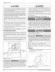
1.
Burner
orifices
for
LP
(propane)
gas
are
located
in
bag
attached
to
the
gas
valve.
Size
is
marked
on
orifice.
2.
Conversion
plate.
0
|
SCREWS
GAS
VALVE
FIGURE
15:
Burner
Assembly
10
Johnson
Controls
Unitary
Products