| The IT IF “(W | hy HIGH EFFICIENCY SEALED COMBUSTION GAS FURNACE MODELS: DGAA and DGAH ISO 9001 Certified Quality Management System (Single Stage Downflow Only) For Installation 56 - 90 MBH INPUT (16.41 - 26.38 KW) INPUT In: 1. Manufactured (Mobile) Homes 2. Recreational Vehicles & Park Models 3. Modular Homes & Buildings LIST OF SECTIONS SAFETY 2... cece cece cece cece ee eee eee eee eee DUCTWORK ...... 2. cece eee cee eee ee eee eet eee RETURN AIR REQUIREMENTS ........2. 22.
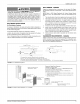
129098-UIM-H-1011 SPECIFIC 1. 2. SAFETY RULES AND PRECAUTIONS e. The external static pressure of the air distribution system ductwork must be set for heating operation to be at least 0.10 to 0.20 inches water column, based on the input rate of the furnace, with the lower value for input rates less than 55,000 btu/hr and the upper value for units with input rates above f. The furnace and ductwork should Only Natural gas or Propane (LP) gas are approved for use with this furnace.
129098-UIM-H-1011 Manufactured « Federal homes INSPECTION in the U.S.A.: Manufactured Home Construction & Safety Standard (H.U.D. Title 24, Part 3280). + National Fuel Gas Code (ANSI-2223.1, + National Electrical Code (NFPA 70). Manufactured homes NFPA-54). in Canada: « Natural Gas and Propane Installation Code (CAN/CSA « Canadian B149.1). Electrical Code, Part 1 (CSA C22.1) FURNACE Recreational Vehicles in U.S.A.
129098-UIM-H-1011 TABLE 1: Unit Clearances to Combustibles Top Application] Front Sides Roof Jack Flue Floor Duct! Closet | Alcove | Closet | Alcove | Closet | Alcove | Closet | Alcove | Closet | Alcove | Closet | Alcove | Closet | Alcove In. (cm) | In. (cm) In. (cm) | In. (cm) | In. (cm)| Downflow | 2(50.8) | 2(50.8) . Rear |6(15.24)|24(60.96) 0 In. (cm) | In. (cm) ] In. (cm) | In. (cm) | In. (cm) | In. (cm) 0 0 0 0 0 In. (cm) | In. (cm) | In.
129098-UIM-H-1011 DUCT | AWARNING The supply air temperature MUST NEVER exceed the Maximum Supply Air Temperature, specified on the nameplate. Operating the furnace above the maximum supply air temperature will cause the heat exchanger to overheat, causing premature heat exchanger failure. Improper duct sizing, dirty air filters, incorrect manifold pressure, incorrect gas orifice and/or a faulty limit switch can cause the furnace to operate above the maximum supply air temperature.
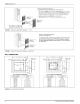
129098-UIM-H-1011 Furnace to Closet Door Clearance — Greater than 1 Inch (2.54 cm) and Up to 5 (12.7 cm) Inches 1. The closet door MUST have a minimum of 250 Inches’ (1613 cm’) of free area in the upper half of the door and a minimum of 50 Inches? (322 cm”) of free area in the lower area of the door. The lower closet door grille may be omitted if an undercut of 2-1/2 inches (16.1 cm) is provided in the door. 2. A fully louvered closet door MUST 250 IN.
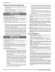
129098-UIM-H-1011 NOTE: REAR WALL OF ENCLOSURE 2.314 (7.0 om) CEILING CUT-OUT FOR ROOF JACK FLOOR CUT-OUT FOR DUCT CONNECTOR I ~ ct €|35 5 T | t soo 8 In € 2 we \ s 1 | 8 a _ ti | 1 2-1/8 (5.4.0m) = * t I | | | OPTIONAL GAS T OR ELECTRIC | ENTRANCE OF FURNACE - 6-3/8] }— om) 4-1/8 | 3-4 jl 9-3/4 —} ; 24.8 om) Recommended (2.9 cm) \ (83cm) 20 (50.
129098-UIM-H-1011 NOTE: Obtain plate. See label on coil panel for conversion and lighting instructions. a temperature rise within the ranges specified on the name SECTION Ill: RETURN REQUIREMENTS CLOSET AIR INSTALLATIONS Additional Requirements Additional requirements for floor and ceiling return installed sealed combustion heating appliance are paragraph. / AUTOMATIC DAMPER _AWARNING HAZARD OF ASPHYXIATION, FLOOR OPENING.
129098-UIM-H-1011 SECTION IV: FILTERS a. if the standard throwaway filter are used the external filter grille must have a minimum area of 540 in? (3483 cm?) which would equal a 15" X 36" filter grille. b. if the Pleated Media or Washable Filters are used the external filter grille must have a minimum area of 684 in? (4413 cm?) which would equal a 18" X 38" filter grille. The increased area is to reduce the pressure drop across the air filter. c.
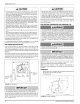
129098-UIM-H-1011 A CAUTION A CAUTION The gas valve body is a very thin casting that cannot take any external pressure. Never applya pipe wrench to the body of the gas valve when installing piping. A wrench must be placed on the square hub located on the gas inlet side of the valve. Placing a wrench to the body of the gas valve will damage the valve causing improper operation and/or the valve to leak.
129098-UIM-H-1011 CONVERSION PROCEDURE IMPORTANT A CAUTION The gas supply must be shut off prior to disconnecting the electrical power, before proceeding with the conversion. HAZARD 1. Shut off gas supply at valve upstream from furnace or at meter as required. Refer to Figure 714. 2. Disconnect gas supply piping from gas valve on furnace. 3. Disconnect electrical wires from gas valve, noting which wires are connected to which terminals. 4.
9098-UIM-H-1011 TABLE 4: High Altitude Duration Chart NATURAL . Elevation Feet 56,000 — Input Orifice | Drill Meters) “bia | size | Orifice | Drill Pat* | pia | size | Sea Level 0.136 | 29 |9051-1361| 2,000 618 | 0.136 | 20 | 9951-1361] 3,000 974 | 0.128 | 30 | 9951-1281] 4,000 7219 | 0.128 | 30 |9051-1281| 5000 7524 | 0.128 | 30 |9051-1281| 6,000 7829 | 0.128 | 30 |9051-1281| 7,000 3134 | 0.120 | 31 19951-1201] 8,000 2438 | 0.120 | 31 | 9951-1201} 9,000 2743 | 0.
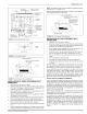
129098-UIM-H-1011 Eighteen gauge thermostat wire is highly recommended. ROOM FURNACE THERMOSTAT CONTROL RETR Smaller gauge thermostat wire may be used only if the guideline below is followed. Thermostat Wire Length (Furnace to Thermostat) Thermostat Wire Gauge 0 - 45 feet 0 - 70 feet 22 20 FIGURE 17: Wiring for Heat Only Thermostat ROOM THERMOSTAT 2 w Do not use the thermostat wire smaller than 22 gauge.
129098-UIM-H-1011 It is recommended that the appliance is installed in a location where the space temperature is 32 °F (0°C) or higher. If the appliance is installed in a location where the ambient temperature is below 32 °F (0°C), the combustion by-products could condense causing damage to the appliance heat exchanger and/or the Roof Jack. 3.
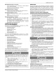
129098-UIM-H-1011 DGAH SWIVEL FLASHING ADJUSTS FROM SLANT FLASHING 0/12 TO 5/12 PITCH 3/12 PITCH FURNACES DGAA FURNACES INSTALLATION DIMENSIONS “w ADJUSTABLE INSTALLATION DIMENSIONS “B" ADJUSTABLE HEIGHT HEIGHT 4000-7101/C 4000-6101/A 70” to 79” 86" to 95” 4000-7121/C 4000-6121/A 75” to 86” 91” to 102” 4000-7141/C 4000-6141/A 83" to 104” 99” to 120” 4000-7151/C 4000-6151/A 90” to 116” 106” to 132” 4000-7171/C 4000-6171/A 127” to 157” 143” to 173" "The 4084-7141 is dimensionall
129098-UIM-H-1011 DGAH SWIVEL FLASHING ADJUSTS FROM SLANT FLASHING 0/12 TO 5/12 PITCH 3/12 PITCH FURNACES INSTALLATION DGAA FURNACES DIMENSIONS INSTALLATION “h ADJUSTABLE HEIGHT DIMENSIONS “B” ADJUSTABLE HEIGHT 4000-8161/C 4000-9161/A 85” to 101” 101” to 117” 4000-8181/C 4000-9181/A 99” to 129” 115” to 145” CAREFULLY CAULK ALL AROUND SWIVEL JOINT WITH SEALANT SUPPLIED BY FURNACE MANUFACTURER. a) 4 an) CAULK —— CAULK UNDER FLASHING UNDER FLASHING .
129098-UIM-H-1011 EXTERIOR upper and lower cap. Remove the two (2) screws that secure the upper cap to the crown assembly base and remove the upper cap. Next, CONNECTING remove the three (3) screws er =| fe YL that secure the lower cap to the crown assembly base. Set bothcaps aside for later use. EXTENSION Available to comply with instances in which the roof jack crown needs to be raised to meet a roof clearance requirement. One extension will raise the roof jack crown by 18 inches.
129098-UIM-H-1011 A CAUTION COMBUSTION AIR PIPE AND FLUE ASSEMBLY THIS JOINT MUST BE BELOW CEILING INTERIOR EXTENSION (OPTIONAL) Use 1/2” (1.27 cm) blunt or sharp end sheet metal screws to fasten roof jack combustion air pipe to furnace combustion air collar Screw holes are provided in pipe and collar. Excessively long screws may extend to flue pipe and puncture it. If substitute screws are used, they must not exceed 7 1/2” (3.81 cm) in length.
129098-UIM-H-1011 VENT TERMINAL FIXED CLOSED ~ @® AIR SUPPLY AREA WHERE TERMINAL IS NOT PERMITTED FIGURE 27: Home Layout Canadian Installations’ US Installation? A.Clearance above grade, veranda, porch, deck, or balcony 12 inches (30 cm) 12 inches (30 cm) B. Clearance to window or door that may be opened 12 inches (30 cm) for models <100,000 BTUH (30 kW), 36 inches (91 cm) for models > 100,000 4 Feet BTUH (30 kW) C.Clearance to permanently closed window 4 Feet 4 Feet D.
129098-UIM-H-1011 CARBON MONOXIDE POISONING HAZARD Failure to follow the steps outlined below for each appliance connected to the venting system being placed into operation could result in carbon monoxide poisoning or death. The following steps shall be followed for each appliance connected to the venting system being placed into operation, while ail other appliances connected to the venting system are not in operation: 1. Inspect the venting system for proper size and horizontal pitch.
129098-UIM-H-1011 TOOLS AND INFORMATION THAT WILL BE REQUIRED IN ORDER TO PROPERLY PERFORM FURNACE START-UP PROCECURE. 1. THE FIRE OR EXPLOSION HAZARD Call the local gas supplier to obtain heating value of the natural gas. if you cannot obtain the heating valve of the gas from the gas supplier, you may use a default value of 1030 BTU/SCF (38.8 MJ / m?). 2. You will need a thermometer or portable digital read the supply and return air temperatures. 3.
129098-UIM-H-1011 In the USA use the following formula to calculate the furnace input. For natural gas multiply the heat content of the gas BTU/SCF or Default 1030 BTU/SCF (38.4 Mu/m?), times 2 cubic ft. (0.056 m) of gas measured at the gas meter, times a barometric pressure and temperature correction factor of 0.960; times 3600, then divided by the time (In seconds) it took to measure 2 cubic ft. (0.056 m) of gas from the gas meter.
129098-UIM-H-1011 A CAUTION Be sure to relight any gas appliances Start of this input check. CHECKING 1. that were 1. Refer to Figure 29 for location of pressure regulator adjustment cap and adjusiment screw on main gas vaive. 2. Turn gas and electrical supplies on and follow instructions to place the unit back in operation. 3.
129098-UIM-H-1011 MANIFOLD PRESSURE “U” TUBE CONNECTION TRANSFORMER (a LINE VOLTAGE BLACK - HIGH SPEED HEAT ® HL GAS VALVE FAN OFF JUMPER t 3.5 IN (0.87 kPa) WATER COLUMN GAS PRESSURE SHOWN FIGURE 30: FAN ON re ADJUSTMENT] JUMPER OF TEMPERATURE I SOOlE 0 Reading Gas Pressure ADJUSTMENT RISE ADANGER limitations shown in Table 7 “ELECTRICAL AND PERFORMANCE DATA”.
129098-UIM-H-1011 TABLE 9: Blower Performance CFM - Downflow Without Filters STANDARD HEATING BLOWERS BTU/H (kW) Nominal Input/Output | CFM(m*/min) | EXTERNAL Speed | Cabinet Tap 0.4 (0.025) Size 56/45 (16.4/13.1) | 1305 (37) A 1425 | 1305 (37) A A 35.3 | 1180 | 33.4 34.0 | 1135 | 32.2 Low No Coil 1250 | 34.1 1145 | 32.4 | 1085 | 30.7 | 1030 | 29.2 28.8 A Nominal Input/Output | CFM(m*/min) | 77/62 (22.5/18.5) | 1725(48.9) | 90/72 (26.3/21.1) | 1725 (48.9) | 32.
SEE NOTE | ooSs.
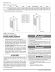
ee agnols DIAGRAMME ELEMENTAIRE CONNECTION (DIAGRAMME POWER SUPPLY (ALIMENTATION 115-I-60 SEE NOTE 118-I-60 To | NOTE I) {MOTEUR DE SOUFFLERIE) (RELAIS craur 70) COOL _(CLIM) a 4 /3 BRN BRN GND (EN TERRE} IRC 8 BRN RELAY CAUTION u IN aoe DprA PRECAUTION D'INDUCT] ma ToMETER wt - BLK oom = na VENTOR L! |) (RELAIS OPEN ALL DISCONNECTS BEFORE SERVICING THIS UNIT - MOTOR OTEUR SCUFFLERIE) BLK HEAT {CHAUF) OUVREZ LES DISSONCTEURS AVANT GE PROCEDER AVEC LE SERVICE BLOWER (E
NOTES Subject to change without notice. Published in U.S.A. Copyright © 2011 by Johnson Controls, Inc. All rights reserved. Johnson Controls Unitary Products P.O.