
Installation guide


035-20530-001Rev.B(0804)
FIGURE 31: Install warning label directly below rating
plate on vestibule panel.
B. Install Auxiliary Limit Switch Assembly
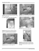
FIGURE 34: Remove blower support shelf (7 screws).
FIGURE 32: Remove Blower Assembly Mounting
Screws (4). Unplug blower motor from control box.
Remove wire clamp. Remove blower assembly.
FIGURE 35: Remove blower support shelf.
FIGURE 33: Remove wires from upper limit.
FIGURE 36: To protect side wall insulation insert
cardboard sheet as a "shoe horn" to insert auxiliary
limit switch assembly between insulation and heat
exchanger.
8 Unitary Products Group