
Installation guide


035-20530-001Rev.B(0804)
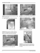
FIGURE 19: Insert Part B and rotate upwards.
FIGURE 20: Place Part B over stud bolts in Part A.
insert Part C and rotate upwards.
Place Part C over stud bolts in Part A.
install stainless steel nuts.
FIGURE 22: Again push assembled liner as far to front
as )ossible and tighten all (4) stainless steel nuts.
FIGURE 23: Inspect with light to make sure Part A, B,
and C are pushed outward against drum.
FIGURE 21: Install stainless steel nuts found in
hardware bag. Do not tighten.
FIGURE 24: Reinstall burner chute to original position.
6 Unitary Products Group