
Installation guide


035-20530-001Rev.B(0804)
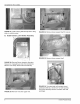
FIGURE 43: Install new wire clamp in blower shelf hole
on rear left-hand side of shelf. Reinstall (7) screws to
secure blower shelf.
FIGURE 46" Install new wiring diagram over existing
diagram.
FIGURE 44: Install new auxiliary limit switch leads in
series with upper limit per wiring diagram.
FIGURE 47: Install danger label on vestibule panel just
below upper limit switch.
FIGURE 45" Install and secure blower on shelf. Plug
blower motor into control box.
FIGURE 48: Turn gas supply back on and leak check
gas valve piping connection.
10 Unitary Products Group