
Installation guide


035-20530-001Rev.B(0804)
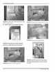
FIGURE 37: Bow back plate of auxiliary limit switch
assembly to insert on right-hand side of blower
compartment.
FIGURE 40: Outer plate should compress against side
casing foil (Cut-away view).
FIGURE 38: Compress stainless loop in middle to slide
past heat exchanger. Do not skin or scrape foil from
insulation while sliding switch down side of heat
exchanger.
FIGURE 41 : Push flange in until clearance holes line
up with holes in blower shelf support bracket
(Cut-away view).
FIGURE 39: Remove "shoe horn".
FIGURE 42: Reinstall blower shelf. Pass wires up
through back slot of blower shelf before locating to final
position.
Unitary Products Group 9