
Installation guide


035-20530-001Rev.B(0804)
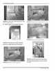
FIGURE 3: Gas valve removal
5. Remove the burner assembly. See Figure 4.
When burner is removed, check the ribbon porting, located in
the end of the burner to insure it is concentric and square.
Reference Figure 5. Check the seams between the burner
halves to insure that they are completely closed and tight.
The flame spreader needs to be checked for proper align-
ment and to insure that it is not distorted and the burner
mounting legs should also be checked for distortion. If any of
these items are found to be out of alignment, the burner
should be replaced..
C. Inspect Heat Exchanger
1. Insert inspection mirror through burner opening. Use
flashlight or droplight to illuminate surface. Inspect
entire interior perimeter of heat exchanger. Note con-
dition per following guidelines.
a. Typical Discoloration Pattern
i. Surface must be smooth shape with no bumps
or indentations.
ii. Normal heat pattern may include light to dark
gray discoloration. See Figure 6.
iii. If visual inspection does not reveal any defor-
mation, crack, or burn through of the heat
exchanger surface, then you need to check the
entire inside surface of the heat exchanger by
feel. If you feel any roughness, deformation,
crack or burn through, proceed with replacing
the heat exchanger with 37323713001.
FIGURE 6: Typical discoloration pattern
b. Cracked. See Figure 7.
FIGURE 4: Burner assembly removal
FIGURE 7: Cracked heat exchanger
c. Deformed. See Figure 8.
FIGURE 5: Burner inspection
Unitary Products Group 3