INSTALLATION INSTRUCTIONS ANSI/BHMA - A156.
CL600_Installationspage2c.
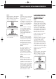
BOX CONTENTS CHECK OPERATION OF THE CODED FRONT PLATE On models CL605, CL615 and CL625 a free passage function is available. This is identified by a black dot on the bottom left hand ’Z’ button. In normal operation the code needs to be entered every time to retract the latch. To put the lock into free passage mode, first press the random factory set code, followed by the passage set button. The lock will now be in code free access mode.
MODEL CL600/605 INSTALLATION INSTRUCTIONS The model CL600/605 is intended to replace the conventional door furniture fitted to an existing mortice latch, or an existing mortice lock which has both a spring latch and a deadbolt. The square follower should be 8mm (5/16”) square. Any lock and key mechanism is retained to operate the deadbolt. The CL600/605 will only operate the latchbolt and not the deadbolt.
MODEL CL600/605 INSTALLATION INSTRUCTIONS STEP 2 Take the BLUE or RED tipped spindle and fit to the code side according to the hand of your door (see diagram). Fit remaining spindle to inside - non code side. STEP 3 Cut three of the socket head bolts to the required length for your door. Approximate overall length should be door thickness plus 25mm (1”), to allow about 10mm (3/8”) of threaded bolt to enter the outside plate. STEP 4 Remove plastic insert plug from frontplate.
MODEL CL600/605 INSTALLATION INSTRUCTIONS STEP 2 (continued) Fit remaining spindle to inside - non code side. STEP 3 Take the adaptor kit, item 13 on the contents page. Cut the two M5 countersunk head bolts to length to suit the door thickness; i.e. door thickness plus a maximum of 10mm (3/8”) (no more than 5mm (3/16”) should enter the front plate). Hold the front plate, with the three hole neoprene seal, against the door over the protruding spindle.
MODEL CL610/615 INSTALLATION INSTRUCTIONS The model CL610/615 has a tubular, deadlocking, mortice latch and may be used as a new installation on a door, or where an existing latch is to be replaced. When installing on a fire door, fire kit is required. Please refer to instructions on page 12 and 13. N.B. Ensure enough room for the latch support post Please align the template to suit the locks backset: 60mm (23/8”) standard or 70mm (23/4”).
MODEL CL610/615 INSTALLATION INSTRUCTIONS STEP 7 Take the BLUE or RED tipped spindle and fit to the code side according to the hand of your door (see diagram). Fit remaining spindle to inside - non code side. 8 STEP 8 Fit the latch support post into back of the code side front plate according to the hand of your door, A for a right hand door, or B for a left hand door (see diagram). STEP 9 Cut three of the socket head bolts to the required length for your door.
MODEL CL620/625 INSTALLATION INSTRUCTIONS The model CL620/625 has a mortice lock and may be used as a new installation on a door, or where an existing lock is to be replaced. IMPORTANT: The mortice lock provided (fig.2 - page 11) has features which are not found in most other locks and so it is recommended that you familiarise yourself with them as follows: A.
MODEL CL620/625 INSTALLATION INSTRUCTIONS STEP 1 STEP 4 STEP 8 Lightly mark a height line on the edge and both faces of the door, and the door jamb, to indicate the top of the lock when fitted. Mark a line down the centre of the door edge, extending above the height line and 300mm (12”) below it. Fold the template accurately along the dotted line and tape it to the door face with the top in line with the height line, and the fold on the door edge. Mark the centres of all the holes to be drilled.
MODEL CL620/625 INSTALLATION INSTRUCTIONS STEP 11 Check that the lever handles are correctly fitted for the hand of door. To change the hand of a lever handle, loosen the grub screw with the small Allen key, reverse the lever handle and fully tighten the grub screw. STEP 12 Before closing the door, enter the code and check that the latchbolt will retract when the lever handle is depressed. Now check the operation of the inside lever handle.
FIRE KIT INSTALLATION INSTRUCTIONS Take time to be precise and finish the job quicker Installation holes must be drilled in exactly the correct positions and precisely at right angles to the door surface. Lock components must be vertically and horizontally accurate in relation to each other and to the door.
EXPLODED DIAGRAM SHOWING FIRE KIT 6 5 4 3 2 1 9 8 7 Fire kit parts 1 2 3 4 5 Fixing Posts x 3 Outer Cover Plate Spindle Washers x 8 Inner Cover Plate Fixing Bolts x 3 6 7 8 9 Short Fixing Bolts x 3 Fire Latch 70mm (2 3/4”) T Strike Plate Fire Cup 13
BACK TO BACK AND PK VERSIONS Back to Back and PK versions - Models CL600/610/615BB & CL600/605PK A) The CL600 range is available in Back to Back versions where the code is on both sides of the door. To install the Back to Back versions: Follow instructions as for non back to back versions substituting the backplate and handle 2, with the coded plate with the through fixing holes. Please note that each side may be coded with the same or different codes.
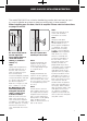
DIMENSIONS 35 - 60mm (1⅜” - 2⅜”) 185mm (7¼”) 110mm (45/16”) Model CL600/605 For use with existing lock 58mm (25/16”) 73mm (2⅞”) 60mm (2⅜”) 87mm (37/16”) Model CL610/615 With tubular latchbolt 235mm (9⅝”) 72mm (2⅞”) 55mm (23/16”) 84mm (35/16”) Model CL620/625 With full ‘Panic Function’ mortice lock & cylinder 15
II-CL600-0812 www.codelocks.com CODELOCKS LTD UK Tel: +44 (0) 1635 239645 Fax: +44 (0) 1635 239644 sales@codelocks.co.uk CODELOCKS INC US Tel: 001 714 979 2900 Fax: 001 714 979 2902 sales@codelocks.us Helpline, service & spares FREEPHONE 0800 393 405 Help:1.877.