User Manual Code Reader™ 1400 Manual Version 03 Release Date: June 2012 C006819_03_CR1400_User_Manual C006819_03_CR1400_UserManual
Statement of Agency Compliance The Code Reader™ 1400 (CR1400) has been tested for compliance with FCC regulations and was found to be compliant with all applicable FCC Rules and Regulations. IMPORTANT NOTE: To comply with FCC RF exposure compliance requirements, this device must not be colocated or operate in conjunction with any other antenna or transmitter.
Code Reader™ 1400 User Manual Copyright © 2012 Code Corporation. All Rights Reserved. The software described in this manual may only be used in accordance with the terms of its license agreement. No part of this publication may be reproduced in any form or by any means without written permission from Code Corporation. This includes electronic or mechanical means such as photocopying or recording in information storage and retrieval systems. NO WARRANTY. This technical documentation is provided AS-IS.
Table of Contents 1.0 - Unpacking............................................................................................................................................................... 1 2.0 - Attaching/Detaching a Cable.................................................................................................................................... 1 3.0 - Powering the Reader On/Off.....................................................................................................................
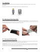
1.0 - Unpacking Remove the CR1400 from its packing and inspect it for damage. If the reader was damaged during shipping, please call Code at (801) 495-2200. Depending on the kit ordered, a USB or RS232 Affinity® cable has been included with your reader. USB Affinity® Cable RS232 Affinity® Cable w/ Power Supply 2.0 - Attaching and Detaching a Cable To attach a cable, plug the RJ-50 end of the Affinity® cable into bottom of the reader handle (Figure 1).
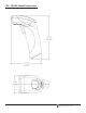
4.0 - Using a CR1400 Out of a Universal Stand Press and hold the CR1400 trigger, the two blue bars emitting from the reader are used for targeting. Center the blue bars in the middle of a bar code. The optimal reading distance from reader to bar code is approximately 4.0” (10 cm). Once the reader is at the optimal distance, the reader will read the bar code. The CR1400 will beep, flash a green LED and vibrate to indicate a ‘good read’ has occurred.
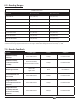
6.0 - Reading Ranges CR1400 Performance Test Code Min Inches (mm) Max Inches (mm) 3 mil Code 39 3.9” (100 mm) 5.0” (125 mm) 7.5 mil Code 39 2.2” (55 mm) 8.0” (205 mm) 13 mil UPC 2.0” (50 mm) 10.8” (275 mm) 4.2 mil Data Matrix 3.7” (95 mm) 4.7” (120 mm) 5 mil Data Matrix 3.7” (95 mm) 5.5” (140 mm) 6.3 mil Data Matrix 3.1” (80 mm) 6.3” (160 mm) 10 mil Data Matrix 1.6” (40 mm) 7.9” (200 mm) 20.8 mil Data Matrix 1.6” (40 mm) 12.
.0 - Symbologies Defaulted On The following are symbologies that have a default of ON. To turn symbologies on or off, scan the symbology bar codes located in the CR1400 Configuration Guide located on our website at http://www.codecorp.com. Aztec Codabar Codablock F Code 11 Code 39 Code 39 Short Margin Code 93 Code 128 Code 128 Short Margin Data Matrix All GS1 DataBar Interleaved 2 of 5 MSI Plessy NEC 2 of 5 PDF417 QR Code Telepen UPC UPC Short Margin 9.
11.0 - Reader ID and Firmware Version To find out the Reader ID and firmware version, open a text editor program (i.e., Notepad, Microsoft Word, etc.
12.
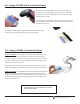
13.0 - USB Cable Example with Pinouts See Section 15.0 for complete reader pinouts descriptions. NOTES: 1. Part to be ROHS and Reach compliant. 2. Maximum Voltage Tolerance = 5V +/- 10%. 3. Caution: Exceeding the maximum voltage will void manufacturer warranty. 14.0 - RS232 Cable Example with Pinouts NOTES: 1. Part to be ROHS and Reach compliant. 2. Maximum Voltage Tolerance = 5V +/- 10%. 3. Caution: Exceeding the maximum voltage will void manufacturer warranty. See Section 15.
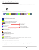
15.0 - Reader Pinouts The connector on the CR1400 is an RJ-50 (10P-10C). The pinouts are as follows: Pin 1 +VIN (5v) Pin 2 USB_DM Pin 3 USB_DP Pin 4 RS232 TX (output from reader) Pin 5 RS232 RTS (output from reader) Pin 6 RS232 RX (input to reader) Pin 7 RS232 CTS (input to reader) Pin 8 External Trigger (active low input to reader) Pin 9 N/C Pin 10 Ground 16.0 - CR1400 Maintentance The CR1400 needs only a minimum of maintenance to operate.
17.0 - Warranty Code’s CR1400 carries a five year limited warranty as described herein. Universal Stands follow the warranty of the reader, and Cables have a 90 Day warranty period. Limited Warranty Code manufactures its hardware products in accordance with industry-standard practices. Code warrants its products will be free from defects in materials and workmanship, provided that the products are used under normal operating condition intended by the Manufacturer.