Bar Code Reader Models 1000/1002 USER'S MANUAL 2190 Regal Parkway Euless, TX 76040 (817) 571-9015 (800) 648-4452 FAX (817) 685-6232
FCC NOTICE WARNING: This equipment generates, uses and can radiate radio frequency energy and if not installed and used in accordance with the instruction manual, may cause interference to radio communications. It has been tested and found to comply with the limits for a Class A computing device pursuant to Subpart J of Part 15 FCC Rules, which are designed to provide reasonable protection against such interference when operated in a commercial environment.
TABLE OF CONTENTS Introduction ......................................................................................................... 1 Installation Instructions ....................................................................................... 2 Scanning Bar Codes ........................................................................................... 5 Wand Scanning .................................................................................... 5 Slot Reader (Badge Reader) ................
TABLE OF CONTENTS (Cont) Appendix A - Function & Special Keys ........................................................ A-1 Appendix B - Code 39 Specifications .......................................................... B-1 Appendix C - Full ASCII Extension to Code 39 ........................................... C-1 Appendix D - UPC Specifications ................................................................ D-1 Appendix E - EAN Specifications ................................................................
INTRODUCTION The Model 1000/1002 bar code reader is an easy to use system that accepts a wand or slot reader as an input device. The reader installs quickly between the keyboard and personal computer. Data is sent to the computer as if it were typed in from the keyboard. No hardware or software changes are necessary. Tailor the reader to individual applications by simply scanning a bar code from the menu.
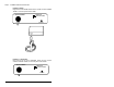
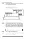
INSTALLATION INSTRUCTIONS OVERVIEW Installation requires connecting cables between the reader and your computer. Step 1: Turn OFF the power to the computer. Step 2: Unplug the KEYBOARD cable from the back of the computer and plug it into the connector labeled "KEYBOARD" on the rear panel of the reader. COMPUTER KEYBOARD Step 3: Plug one end of the cable (supplied with the reader) into the connector labeled "COMPUTER" on the rear panel of the reader.
Step 5: CONNECTING INPUT DEVICES: Installing a Wand Plug the end of the WAND cable into the circular connector labeled "WAND" on the front panel of the reader. MICROSCANNER AMERICAN MICROSYSTEMS POWER WAND Installing A Slot Reader Plug the end of the SLOT READER cable into the circular connector labeled "WAND" on the front panel of the reader.
Step 6: Verify that the cables are connected as shown below: Step 7: Turn ON the power to the computer. (The reader receives its power from the computer just like the keyboard.) Step 8: The "POWER" display light on the front panel of the reader will display RED and the reader will BEEP twice. Approximately 1/2 second later the display will change to GREEN. Step 9: The GREEN color indicates the reader is ready to use. The keyboard remains fully functional and you may enter data as before.
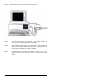
SCANNING BAR CODES WAND SCANNING Step 1: HOLD THE WAND LIKE A PENCIL, tilted at an angle of 10o to 30o from vertical. Step 2: TOUCH the wand tip to the WHITE SPACE before the label. Step 3: Move the wand QUICKLY across the label as if you were drawing a straight line through the middle of it. Step 4: Begin and end your stroke in the WHITE SPACE. Maintain a smooth, even stroke while scanning.
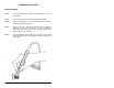
SLOT READER (Badge Reader) Step 1: Hold the CARD so that the bar code label is on the bottom and FACES the ARROW on the slot reader. Step 2: Insert the CARD into the opening on either side of the reader. Step 3: Holding the CARD flat against the bottom of the reader, SLIDE the card through the opening. You can slide the CARD bi-directionally (either left-to-right or right-to-left) and the data will output correctly to your computer.
DEFAULT SETTINGS The Model 1000/1002 is shipped from the factory with the following default settings: CODE 39 CODE 39 DECODER FULL ASCII MOD 43 CHECK DIGIT SEND CHECK DIGIT CONCATENATE M ODE UPC ON OFF OFF OFF OFF UPC DECODER CONVERT UPC-E TO UPC-A CONVERT UPC-A TO EAN-13 SEND UPC-A NUMBER SYSTEM SEND UPC-E NUMBER SYSTEM SEND UPC-A CHECK DIGIT SEND UPC-E CHECK DIGIT EAN EAN DECODER ZERO FILL EAN-8 TO EAN-13 SEND EAN-13 COUNTRY CODE SEND EAN-8 COUNTRY C ODE SEND EAN-13 CHECK DIGIT SEND EAN-8 CHECK DIGIT I
PREAMBLE ENTER PREAMBLE PREAMBLE SEND DELAY ACTIVE TYPES POSTAMBLE NONE 0.0 SEC.
CHANGING THE DEFAULT SETTINGS You can easily change the default settings by simply scanning the bar code options located on the READER SETUP MENU. The READER SETUP MENU is a laminated sheet of bar codes supplied with this manual. The basic programming sequence is: START / CATEGORY / OPTION (0-9) / ON/OFF (or) NUMBER ONLY / EXIT Follow the instructions below to change the settings. Step 1: Scan the START label at the top left corner of the SETUP MENU. This puts the reader into the program mode.
Step 5: If you want to make another change within the SAME CATEGORY, you can scan another option number (i.e., return to "Step 3" above). If you want to make a change in a DIFFERENT CATEGORY you MUST scan the new CATEGORY (i.e., return to "Step 2" above and repeat the steps). Step 6: When you have finished making all of the changes, you can either: 1) SCAN the EXIT (Save Changes) label to save all the changes OR 2) SCAN the EXIT (Ignore Changes) label to exit without saving any changes.
PROGRAMMING GUIDE START The START bar code places the reader into the program mode. After scanning this label, the reader will emit three short BEEPS to indicate that it is in the program mode. EXIT (SAVE CHANGES) Scan this bar code to EXIT the program mode and save all of the changes. After scanning this label, the reader will BEEP twice, then delay approximately one second, and emit three short BEEPS to indicate that it accepted the changes.
* NOTE: Defaults are marked with " * ". CODE 39 0) CODE 39 DECODER ON * Enable reading CODE 39 labels. OFF 1) FULL ASCII ON OFF * Disable reading CODE 39 labels. Enable the FULL ASCII EXTENSION to CODE 39. Option (0) above must be ON. A Full ASCII Chart is provided in Appendix C. Disable the FULL ASCII EXTENSION to CODE 39. This sets the reader to the standard CODE 39 mode. 2) MOD 43 CHECK DIGIT ON Enable the MOD 43 CHECK DIGIT for CODE 39.
UPC 0) UPC DECODER ON * Enable reading UPC-A and UPC-E labels. OFF Disable reading UPC-A and UPC-E labels. 1) CONVERT UPC-E TO UPC-A ON Convert all UPC-E labels to their UPC-A equivalents before transmission. After conversion, the reader will follow the UPC-A programming options. OFF * No UPC-E conversions will be performed. 2) CONVERT UPC-A TO EAN-13 ON Convert all UPC-A labels to an equivalent EAN-13 format by inserting a leading zero.
EAN 0) EAN DECODER ON * Enable reading EAN-8 and EAN-13 labels. OFF Disable reading EAN-8 and EAN-13 labels. 1) ZERO FILL EAN-8 TO EAN-13 ON Add five leading zeroes to EAN-8 labels. After conversion, the reader will follow the EAN-13 programming options. OFF * No conversion is performed. 2) SEND EAN-13 COUNTRY CODE ON * Transmit the EAN-13 COUNTRY CODE. OFF Do not transmit the EAN-13 COUNTRY CODE. 3) SEND EAN-8 COUNTRY CODE ON * Transmit the EAN-8 COUNTRY CODE.
UPC/EAN SUPPLEMENTS 0) SUPPLEMENTS DECODER ON Enable reading UPC & EAN supplements. OFF* Disable reading UPC & EAN supplements. 1) ALLOW 2 DIGIT ON* Enable reading 2 digit supplements. above must be set ON. OFF Disable reading 2 digit supplements. 2) ALLOW 5 DIGIT ON* Enable reading 5 digit supplements. above must be set ON. OFF Option (0) Option (0) Disable reading 5 digit supplements. 3) REQUIRE SUPPLEMENTS Specifies how the reader will handle various supplements.
INTERLEAVED 2 OF 5 0) I 2 OF 5 DECODER ON * Enable reading INTERLEAVED 2 OF 5 labels. OFF Disable reading INTERLEAVED 2 OF 5 labels. 1) CHECK DIGIT: 0=NONE, 1=USS, 2=OPCC Specifies which type of check digit will be used with INTERLEAVED 2 of 5. 0* 1 2 NONE (no check digit required) UNIFORM SYMBOLOGY SPECIFICATION (3-1-3 MOD 10) OPTICAL PRODUCT CODE COUNCIL (2-1-2 MOD 10) 2) SEND CHECK DIGIT ON Transmit the INTERLEAVED 2 OF 5 check digit with the bar code data. OFF * The check digit is not transmitted.
CODABAR 0) CODABAR DECODER ON * Enable reading CODABAR labels. OFF Disable reading CODABAR labels. 1) SEND START/STOP ON Transmit the CODABAR start/stop characters. OFF * Do not transmit the CODABAR start/stop characters. 2) CLSI FORMATTING ON The reader will insert a blank after the 1st, 5th, and 10th characters of a 14-character CODABAR label. The label length does not include the start and stop characters. OFF * Disable CLSI formatting. 3) CLSI CHECK DIGIT ON Enable the CLSI check digit.
CODE 93 0) CODE 93 DECODER ON * Enable reading CODE 93 labels. OFF Disable reading CODE 93 labels. 1) CONCATENATE MODE ON Enable CONCATENATE MODE. The concatenate mode allows the reader to concatenate multiple bar codes in its buffer, then send them to the computer just like they were a single bar code. When a Code 93 label with a leading space is read, the reader emits two short beeps and buffers the data without transmission.
MSI/PLESSEY 0) MSI/PLESSEY DECODER ON Enable reading MSI/PLESSEY labels. OFF * Disable reading MSI/PLESSEY labels. 1) TWO CHECK DIGITS REQUIRED ON Two valid CHECK DIGITS are required for each label. The first check digit is defined by option (2) below. The second check digit is always MOD 10. OFF * One valid CHECK DIGIT is required for each label. The CHECK DIGIT must be MOD 10. 2) FIRST CHECK DIGIT MOD 11 ON The FIRST CHECK DIGIT must be MOD 11. OFF * The FIRST CHECK DIGIT must be MOD 10.
CODE 11 0) CODE 11 DECODER ON Enable reading CODE 11 labels. OFF * Disable reading CODE 11 labels. 1) TWO CHECK DIGITS REQUIRED ON Two valid CHECK DIGITS are required for each label. OFF * One valid CHECK DIGIT is required for each label. 2) SEND FIRST CHECK DIGIT ON Transmit the FIRST CHECK DIGIT. OFF * Do not transmit the FIRST CHECK DIGIT. 3) SEND SECOND CHECK DIGIT ON Transmit the SECOND CHECK DIGIT. OFF * Do not transmit the SECOND CHECK DIGIT.
PREAMBLE 0) ENTER PREAMBLE This set of user-defined characters is transmitted at the beginning of bar code data. To define the PREAMBLE, scan up to 15 characters from the FULL ASCII chart on the reverse side of the SETUP MENU. Scan the "ON" bar code when complete. 1) PREAMBLE SEND DELAY (0.0 - 9.9 SEC) This option specifies the amount of delay to occur after the PREAMBLE is transmitted. The delay period is programmable from 0.0 to 9.9 seconds. The default setting is 0.0 seconds.
BAR CODE EDIT This option allows editing bar codes before transmittal. 0) BAR CODE EDITING (Must be ON for any of the editing options below to be valid.) ON Enable Bar Code Editing. OFF * Disable Bar Code Editing. 1) ENTER # OF LEADING CHARS TO STRIP (0-9, A-F) (Option (0) above must be ON.) Refers to the number (0-15) of bar code characters to be stripped, i.e., removed, from the beginning of the data entry. 2) ENTER # OF TRAILING CHARS TO STRIP (0-9, A-F) (Option (0) above must be ON.
TERMINATION CHARACTER The optional TERMINATION CHARACTER is transmitted at the end of the data. This option applies to bar code, mag stripe, and serial data. If a USER DEFINED TERMINATION CHARACTER is desired, select setting (4) below, then scan a single character from the FULL ASCII section of the MENU.
COMPUTER TYPE This option defines both the type of computer and the type of keyboard that will be used. The selections must be made properly for the data to transmit correctly. Note the UNIVERSAL keyboard setting below, which can be used for all international keyboards.
OTHER OPTIONS 0) SEND BAR CODE TYPE ID ON Transmit the bar code identifier character at the beginning of the bar code data. There is one space between the ID character and the bar code data. The identifier characters are defined below: A B C D E F OFF * CODE 39 UPC-A UPC-E EAN-13 EAN-8 INTERLEAVED 2 of 5 G H I J K CODABAR CODE 128 CODE 93 MSI/PLESSEY CODE 11 Do not transmit BAR CODE TYPE ID. 1) FUNCTION KEYS ON Applies to bar code data, preambles, postambles, and user defined termination characters.
3) KEYBOARD NUM LOCK STATUS Setting this function is necessary only if option (5), KEYBOARD AUTO CAPS/NUM LOCK, does not operate on your computer. See (5) to determine whether KEYBOARD NUM LOCK STATUS is required. To use this option, scan either ON or OFF to match the computer keyboard's NUM LOCK status. ON Scan ON to indicate that the computer keyboard's NUM LOCK is turned ON. OFF * Scan OFF to indicate that the computer keyboard's NUM LOCK is turned OFF.
NOTE The KEYBOARD AUTO CAPS/NUM LOCK option is NOT effective on some computers, such as XT's. Indications that this option is NOT functioning are as follows: Upper/Lower Case are reversed. SPECIAL KEY characters are not transmitted when SPECIAL KEYS are ON. If KEYBOARD AUTO CAPS/NUM LOCK is NOT operating properly on your system, take the following steps: Set KEYBOARD AUTO CAPS/NUM LOCK to OFF. Set KEYBOARD CAPS LOCK STATUS. (See option (2).) Set KEYBOARD NUM LOCK STATUS. (See option (3).
DIAGNOSTICS This option executes a self-test program which performs the following tests on the reader: * EPROM Version Number * Internal and External Ram Test * EPROM Checksum Test * Character Set Test * Buzzer Test The above tests are performed and their status is displayed on the PC monitor. NOTE: Exit your application program and return to DOS before enabling this test.
SPECIFICATIONS BAR CODES SUPPORTED Auto-discriminates between all of the following codes: - Code 39 - Extended Code 39 (Full ASCII) - Interleaved 2 of 5 (Variable and Fixed Length, Check Digit) - UPC-A (Including 2 and 5 Character Supplements) - UPC-E(0), UPC-E(1) (Including 2 and 5 Character Supplements) - EAN (Including 2 and 5 Character Supplements) - Code 128 (UCC-128 Verification, Check Digit) - Codabar - Code 93 - Code 11 - MSI/Plessey INPUT DEVICES SUPPORTED Wands (Visible and Infrared) Slot Readers
SIGNAL DEFINITIONS WAND INTERFACE PIN 1 2 3 4 5 SIGNAL +5V DATA GROUND NO CONNECTION NO CONNECTION 5 1 4 2 3 M1000 KEYBOARD/COMPUTER INTERFACE PIN 1 2 3 4 5 SIGNAL KEYBOARD CLOCK GROUND KEYBOARD DATA +5V SPARE 1 5 4 2 3 M1002 KEYBOARD/COMPUTER INTERFACE PIN 1 2 3 4 5 6 SIGNAL KEYBOARD DATA RESERVED GROUND +5V KEYBOARD CLOCK RESERVED 6 4 30 2 1 5 3
APPENDIX A - FUNCTION & SPECIAL KEYS With FUNCTION KEYS enabled, the decoder can accept a given ASCII character and transmit a corresponding FUNCTION KEY to the computer. The ASCII characters and values are listed in the table below.
APPENDIX B - CODE 39 SPECIFICATIONS Code 39 is a variable length alphanumeric code. Each character is made up of nine elements, five bars and four spaces. Three of the elements are wide and six are narrow. Code 39 is a popular choice for applications because: - it is easy to print with low cost dot matrix printers large character set (A-Z, 0-9, 7 special characters) code can be extended to include the entire 128 ASCII character set variable length.
CODE 39 CHARACTER SET: An optional check character can be used for applications requiring higher levels of data security. When used, the check character immediately follows the last data character. The check digit is calculated as follows: 1.
2. Sum all of the numerical values for each data character in the bar code. 3. Divide this sum by 43. 4. The remainder is the numerical value for the check digit. Use the table in step 1 to look-up the corresponding character. EXAMPLE: Sample Code 39 data = A394T 1. 2. 3. 4. Use the table to lookup the numerical value for each character. 10 + 3 + 9 + 4 + 29 = 55 55 / 43 = 1 remainder 12 Check digit numerical value = 12 The check digit = C.
APPENDIX C - FULL ASCII EXTENSION TO CODE 39 The FULL ASCII EXTENSION expands standard CODE 39 to include the entire 128 ASCII character set. This is accomplished by pairing standard CODE 39 characters.
APPENDIX D - UPC SPECIFICATIONS The Universal Product Code (UPC) symbols can be found on almost all retail products today. The UPC coding system was designed to uniquely identify a product and its manufacturer.
The last digit in UPC bar codes is a MODULO 10 CHECK DIGIT. It is calculated in the following manner: 1. From right to left, sum the digits in the odd positions. 2. Multiply this sum by 3. 3. From right to left, sum the digits in the even positions. 4. Add this sum to the product of Step 2. 5. The modulo-10 check digit is the smallest number, which when added to the sum of Step 4 produces a multiple of 10. EXAMPLE: 1. 2. 3. 4. 5. UPC bar code = 01234567890C where C is the CHECK DIGIT.
The following table illustrates the expansion process for converting UPC-E to its UPC-A equivalent: Version E Number Insertion Digits Insertion Location Resultant Version A XXXXX0 XXXXX1 XXXXX2 XXXXX3 XXXXX4 XXXXX5 XXXXX6 XXXXX7 XXXXX8 XXXXX9 00000 10000 20000 00000 00000 0000 0000 0000 0000 0000 Position 3 Position 3 Position 3 Position 4 Position 5 Position 6 Position 6 Position 6 Position 6 Position 6 XX00000XXX XX10000XXX XX20000XXX XXX00000XX XXXX00000X XXXXX00005 XXXXX00006 XXXXX00007 XXXXX000
APPENDIX E - EAN SPECIFICATIONS The European Article Numbering system (EAN) is a superset of UPC. EAN has two versions: EAN-13 (13 digits) and EAN-8 (8 digits). 5 012345 678900 5012 3452 EAN 13 EAN 8 Country codes 00, 01, 03, 04, and 06 - 09 are assigned to the U.S. for compatibility with UPC.
APPENDIX F - INTERLEAVED 2 OF 5 SPECIFICATIONS The Interleaved 2 of 5 bar code symbology is a numeric code (0 - 9) which has different start and stop characters. The name Interleaved 2 of 5 is derived from the fact that two characters are paired together using the bars to represent the first character and spaces to represent the second. Each character has two wide elements and three narrow elements.
OPTIONAL CHECK DIGIT: Interleaved 2 of 5 may contain an optional check digit. The reader supports two types of check digits: 1. 2. Uniform Symbology Specification (USS) - calculated as modulo 10 check digit based on 3-1-3 weightings. Optical Product Code Council (OPCC) - calculated as modulo 10 check digit based on 2-1-2 weightings. USS CHECK DIGIT CALCULATION: 1. 2. 3. 4. 5. From right to left, sum the digits in the odd positions. Multiply this sum by 3.
APPENDIX G - CODABAR SPECIFICATIONS The Codabar bar code symbology is a numeric code (0 - 9) that also contains six special characters and four start/stop characters. The start/stop characters may or may not be transmitted. Characters are constructed of four bars and three spaces. Codabar is commonly used in libraries, blood banks, cotton and transportation industry.
APPENDIX H - CODE 128 SPECIFICATIONS The CODE 128 symbology is a variable length alphanumeric code containing the full 128 ASCII character set. Each character consists of 11 modules containing three bars and three spaces. Bars and spaces can be from 1 to 4 modules wide. Three different start characters are used to select one of three character sets. Code 128 is the bar code of choice for new applications.
CHARACTER SET: The following table contains the character set for Code 128 subsets A, B, and C: CODE 128 (USD-6) VALUE CODE A CODE B CODE C B S 0 1 2 3 4 5 6 7 8 9 10 11 12 13 14 15 16 17 18 19 20 21 22 23 24 25 26 27 28 29 30 31 32 33 34 35 36 37 38 39 40 41 42 43 44 45 SP ! " # $ % & ' ( ) * + , . / 0 1 2 3 4 5 6 7 8 9 : ; < = > ? @ A B C D E F G H I J K L M SP ! " # $ % & ' ( ) * + , .
CODE 128 (USD-6) VALUE CODE A CODE B CODE C B S 46 47 48 49 50 51 52 53 54 55 56 57 58 59 60 61 62 63 64 65 66 67 68 69 70 71 72 73 74 75 76 77 78 79 80 81 82 83 84 85 86 87 88 89 90 N O P Q R S T U V W X Y Z [ \ ] ^ _ NUL SOH STX ETX EOT ENQ ACK BEL BS HT LF VT FF CR SO SI DLE DC1 DC2 DC3 DC4 NAK SYN ETB CAN EM SUB N O P Q R S T U V W X Y Z [ \ ] ^ _ ` a b c d e f g h i j k l m n o p q r s t u v w x y z 46 47 48 49 50 51 52 53 54 55 56 57 58 59 60 61 62 63 64 65 66 67 68 69 70 71 72 73 74 75 76 77
CODE 128 (USD-6) VALUE CODE A CODE B CODE C B S 91 92 93 94 95 96 97 98 99 100 101 102 ESC FS GS RS US FNC 3 FNC 2 SHIFT CODE C CODE B FNC 4 FNC 1 { ¦ } ~ DEL FNC 3 FNC 2 SHIFT CODE C FNC 4 CODE A FNC 1 91 92 93 94 95 96 97 98 99 CODE B CODE A FNC 1 4 1 1 1 1 1 4 4 1 1 3 4 1 1 1 3 1 1 1 1 1 1 1 1 2 1 1 1 4 4 1 1 3 4 1 1 1 1 3 1 1 3 1 3 1 1 1 1 2 4 4 4 1 1 1 1 4 3 4 3 1 3 1 1 3 1 3 1 1 1 1 1 B S B S B S 2 2 2 1 1 1 1 1 1 4 2 2 1 1 3 2 4 2 B S B S B S B 2 3 3 1 1 1 2
APPENDIX I - CODE 93 SPECIFICATIONS The Code 93 bar code symbology is a variable length alphanumeric code containing the full 128 ASCII character set. Each character consists of 9 modules with three bars and three spaces. The bars can be 1, 2, or 3 modules wide except for the start/ stop character. The spaces can be 1, 2, 3, or 4 modules wide. Code 93 bar codes contain a mandatory two digits for data integrity.
Table 2.
APPENDIX J - SOURCES OF BAR CODE STANDARDS ABC (American Blood Commission) 1117 North 19th Street Suite 501 Arlington, VA 22209-1749 (703) 522-8414 * Committee for Commonality in Blood Banking Automation (CCBBA) Report (Codabar) AIM (Automatic Identification Manufacturers, Inc.
DOD (Department of Defense) Naval Publications & Forms Center 5801 Tabor Avenue Philadelphia, PA 19120 (215) 697-2000 * * * MIL-STD-1189A (B) - Standard Department of Defense Bar Code Symbology MIL-STD-129J - Military Standard - Marking for Shipment & Storage Bar Code Markings FED-STD-123D - Federal Standard - Marking for Shipment (Civil Agencies) Bar Code Markings EAN (European Article Numbering Association) Rue des Colonies, Bte 8 1000 Brussels BELGIUM 011 322 218 7585 HIBCC (Health Industry Business Co