
Operating instructions

Chapter 4 Operating Instructions
CLV63x Bar Code Scanner
34 © SICK AG · Division Auto Ident · Germany · All rights reserved 8011970/S345/2008-04-16
Product description
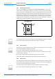
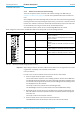
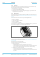
4.7.2 LEDs on the bar code scanner's housing
The bar code scanner's housing has six LEDs that display the operating status, the laser di-
ode's activity, the status of the reading result and the transfer to the RS-232/RS-422/485,
CAN and Ethernet interfaces.
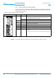
In reading operation the LEDs indicate the following:
Tab. 4-5: LED indications
Important The “Result“ LED is not coupled with one of the “Result 1“ or "Result 2" outputs.
LED Colour Meaning
READY Green
• Lights up constantly after switching on and a successful self-test
• Goes out when parameter values are being uploaded from or
downloaded to the bar code scanner
Red
• Lights up when a hardware error has been detected
RESULT Green
• Lights up after a successful read (Good Read, 100 ms)
LASER Green
• Reading operation: Lights up when the laser diode is switched on
(depends on the reading pulse)
DATA Green
• Lights up during the data transfer for 100 ms
CAN Yellow
• Flickers during the data transfer via the CAN interface
LNK TX Green
• Lights up when the physical Ethernet connection is o.k.
Bar graph
(0 ... 100%)
Green
• LED´s light up according to the reading rate during diagnostic
mode.
• During normal reading mode the bar graph display is switched off.