
Operating instructions

Operating Instructions Chapter 4
CLV63x Bar Code Scanner
Product description
8011970/S345/2008-04-16 © SICK AG · Division Auto Ident · Germany · All rights reserved 21
4 Product description
This chapter describes the design, the features and the functions of the CLV63x Bar Code
Scanner.
¾ For installation, electrical installation and startup assistance as well as for the applica-
tion-specific configuration of the bar code scanner using the SOPAS-ET configuration
software, please read this chapter prior to carrying out any of the tasks.
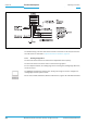
4.1 Setting up the bar code scanner
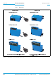
The CLV63x Bar Code Scanner consists of a laser scanner (laser diode and lens) with fixed
focus and an electronic unit with an integrated decoder. The laser scanner and electronic
unit are located in a housing. The ligh exits and enters via a reading window in the industrial-
type housing. The bar code scanner (depending on the version) is electrically connected by
a cable with a connector or a revolving connector unit with two connections.
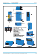
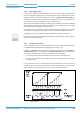
For an adaption to on-site space conditions/reading functions three housings are available:
a housing with front reading window, a housing with side reading window and a housing with
oscillating mirror. Via the integrated angle attachment/oscillating mirror, the laser beam ex-
its through the side reading window at an angle of emergence of 105°. For the oscillating
mirror this corresponds to the central position (default settings) of the laser beam perpen-
dicular to the scan direction.
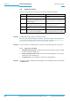
Depending on the type, various lenses enable different resolutions and reading areas.