Operating Instructions O P E R AT I N G I N S T R U C T I O N S CLV63x Bar Code Scanner CLV63x Bar Code Scanner Advanced Line
Software Versions Operating Instructions CLV63x Bar Code Scanner Software Versions Software/Tool Function Version CLV63x Bar Code Scanner SICK firmware From v 1.0 0000 Device Description CLV63x Device-specific software module for SOPAS-ET config- From v 2.5 uration software SOPAS-ET Configuration software From v 2.
Operating Instructions Contents CLV63x Bar Code Scanner Table of contents 1 2 3 4 5 6 7 8 8011970/S345/2008-04-16 Figures and Tables............................................................................................................ 5 Abbreviations..................................................................................................... 5 Tables................................................................................................................. 6 Figures .........
Contents Operating Instructions CLV63x Bar Code Scanner 9 Troubleshooting .............................................................................................................. 75 9.1 Overview of errors and malfunctions which could occur ............................. 75 9.2 Detailed malfunction analysis ....................................................................... 75 9.3 Status protocol................................................................................................ 76 9.
Figures and Tables Operating Instructions Chapter CLV63x Bar Code Scanner Figures and Tables Abbreviations CAN Controlled Area Network (field bus protocol based on the CAN bus) CDB Connection Device Basic CDM Connection Device Modular CLV CMC Code-Leser V-Prinzip Connection Module Cloning CMD Connection Module Device CMF Connection Module Fieldbus CMP Connection Module Power DOF Depth Of Field HTML I Hyper Text Markup Language Input LED Light Emitting Diode MAC Medium Access Control
Chapter Figures and Tables Operating Instructions CLV63x Bar Code Scanner Tables Tab. 1-1: Tab. 2-1: Tab. 2-2: Tab. 4-1: Tab. 4-2: Tab. 4-3: Tab. 4-4: Tab. 4-5: Tab. 4-6: Tab. 5-1: Tab. 6-1: Target group ........................................................................................................9 Required qualification for starting up the bar code scanner ........................ 11 Laser Data of CLV63x ......................................................................................
Operating Instructions Figures and Tables Chapter CLV63x Bar Code Scanner Figures Fig. 2-1: Fig. 2-2: Fig. 3-1: Fig. 4-1: Fig. 4-2: Fig. 4-3: Fig. 4-4: Fig. 4-5: Fig. 4-6: Fig. 5-1: Fig. 5-2: Fig. 5-3: Fig. 5-4: Fig. 5-5: Fig. 5-6: Fig. 5-7: Fig. 5-8: Fig. 6-1: Fig. 6-2: Fig. 6-3: Fig. 6-4: Fig. 6-5: Fig. 6-6: Fig. 6-7: Fig. 6-8: Fig. 7-1: Fig. 8-1: Fig. 8-2: Fig. 10-1: Fig. 10-2: Fig. 10-3: Fig. 10-4: Fig. 10-5: Fig.
Chapter Figures and Tables Operating Instructions CLV63x Bar Code Scanner Fig. 10-7: Fig. 10-8: Fig. 10-9: Fig. 10-10: Fig. 10-11: Fig. 10-12: Fig. 10-13: Fig. 10-14: Fig. 10-15: Fig. 10-16: Fig. 10-17: Fig. 10-18: Fig. 10-19: Fig. 10-20: Fig. 10-21: Fig. 11-1: Fig. 11-2: Fig. 11-3: Fig. 11-4: Fig. 11-5: Fig. 11-6: 8 CLV631: Reading ranges of the line scanner with oscillating mirror (side reading window).......................................................................................
Operating Instructions Notes on this document Chapter 1 CLV63x Bar Code Scanner 1 Notes on this document 1.
Notes on this document Chapter 1 Operating Instructions CLV63x Bar Code Scanner 1.4 Used symbols To gain easier access, some information in this documentation is emphasised as follows: Notice! ¾ Indicates a potential risk of damage or impair on the functionality of the bar code scanner or other devices. Warning notice! A warning notice indicates real or potential danger. This should protect you against accidents.
Operating Instructions Safety information Chapter 2 CLV63x Bar Code Scanner 2 Safety information This chapter deals with your safety and operator safety in the operational area. ¾ Read this chapter carefully before using the bar code scanner. 2.1 Authorised users For correct and safe functioning, the bar code scanner must be installed, operated and maintained by sufficiently qualified staff.
Safety information Chapter 2 Operating Instructions CLV63x Bar Code Scanner 2.2 Intended use The CLV63x Bar Code Scanner is an intelligent sensor for the automatic recognition and decoding of bar codes on objects e.g. in a conveyor system.
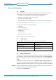
Operating Instructions Safety information Chapter 2 CLV63x Bar Code Scanner 2.3.2 Fig. 2-1: Laser radiation of the bar code scanner Outlet opening of the laser radiation at the reading window (shown here: Ethernet version) Damage to the eyes through laser radiation! The bar code scanner operates with an red light laser of class 2. Looking at the laser's light path for a longer period of time can damage the eye's retina. The entire reading window is the LED radiation outlet opening.
Safety information Chapter 2 Operating Instructions CLV63x Bar Code Scanner Standard version Fig. 2-2: Laser warning sign attached to the bar code scanner at delivery Device CLV630 CLV631 CLV632 Laser out radiation (maximum/average) 3.2 mW/ <1.0 mW 3.2 mW/ <1.0 mW 3.2 mW/ <1.0 mW Emitted wavelength 655 nm 655 nm 655 nm Pulse duration < 300 μs < 300 μs < 300 μs Tab.
Operating Instructions Safety information Chapter 2 CLV63x Bar Code Scanner • "Laser" LED: During normal reading operation the "Laser" LED lights up when the laser diode is switched on. When calling up functions via the two buttons of the bar code scanner (aborting normal reading operation), the LEDs have got additional display functions. The "Laser" LED will differ from its original function.
Chapter 2 Safety information Operating Instructions CLV63x Bar Code Scanner 2.5 Environmental information The bar code scanner has been constructed with minimum environmental pollution in mind. Excluding the housing, the bar code scanner does not contain any materials using silicone. 2.5.
Quick-Start Operating Instructions Chapter 3 CLV63x Bar Code Scanner 3 Quick-Start 3.1 Preparing the bar code scanner for the quick start The bar code scanner can be operated quickly and easily using the supplied SOPAS-ET configuration software.
Chapter 3 Quick-Start Operating Instructions CLV63x Bar Code Scanner 3.3 Performing the reading Note With the SOPAS-ET configuration software, the QUICKSTART register tab contains the most important reading parameters for configuring and performing a bar code reading: PROJECT TREE, CLV63X, QUICKSTART register tab Fig. 3-1: Register tab Quickstart Perform the reading: 1. Ensure that the relevant code types are activated on the register tab. 2. Carry out a test reading with a test bar code.
Operating Instructions Quick-Start Chapter 3 CLV63x Bar Code Scanner Optimise the reading conditions: If no reading result is displayed or if you wish to increase the code reading reliability, the reading can be repeated by taking the following measures. 8011970/S345/2008-04-16 ¾ Install the bar code scanner in such a way that the bar code scanner's light meets the idle object (code) at a 15° angle (skew).
Chapter 3 Quick-Start Operating Instructions CLV63x Bar Code Scanner 20 © SICK AG · Division Auto Ident · Germany · All rights reserved 8011970/S345/2008-04-16
Operating Instructions Product description Chapter 4 CLV63x Bar Code Scanner 4 Product description This chapter describes the design, the features and the functions of the CLV63x Bar Code Scanner. ¾ 4.1 For installation, electrical installation and startup assistance as well as for the application-specific configuration of the bar code scanner using the SOPAS-ET configuration software, please read this chapter prior to carrying out any of the tasks.
Chapter 4 Product description Operating Instructions CLV63x Bar Code Scanner 4.1.1 Fig.
Operating Instructions Product description Chapter 4 CLV63x Bar Code Scanner Fig.
Product description Chapter 4 Operating Instructions CLV63x Bar Code Scanner 4.
Operating Instructions Product description Chapter 4 CLV63x Bar Code Scanner 4.3 Device versions The CLV63x Bar Code Scanner with a glass reading window is available in the following versions, among others: Order no.
Product description Chapter 4 Operating Instructions CLV63x Bar Code Scanner Important Depending on the connection (design), the following interfaces are available: • Standard version (cable with connector) – RS-232, RS-422/485, CAN, two digital switching inputs, two digital switching outputs, power supply • Ethernet version (revolving connector unit) – Connector 1: Ethernet – Connector 2: RS-232, RS-422/485, CAN, one digital switching input, power supply 4.
Operating Instructions Product description Chapter 4 CLV63x Bar Code Scanner • Manipulation of the output of the reading data via event-dependent evaluation condi- Data processing tions • Manipulation of the output strings through filter and output sort options • Host interface: two data output formats configurable, switchable to different physical Data communication interfaces, parallel operation possible • Aux interface: fixed data output format, switchable to different physical interfaces, para
Chapter 4 Product description Operating Instructions CLV63x Bar Code Scanner Fig. 4-3: Bar code scanner's methods of operation in a conveyor system (schematic) The detailed wiring of the bar code scanner and the connections to the host/PC and to the external sensors is described in chapter 6 Electrical installation, page 49. 4.6.1 Reading configuration The bar code scanner detects bar codes with an adjustable scan frequency. The bar code scanner can detect codes on still and moving objects.
Operating Instructions Product description Chapter 4 CLV63x Bar Code Scanner 4.6.2 Object trigger control In order to start an object-related reading process, the bar code scanner requires an appropriate external signal (trigger source) for reporting an object in the reading area. The start signal is emitted via an external reading pulse sensor (e. g. photoelectric reflex switch) as standard.
Chapter 4 Product description Operating Instructions CLV63x Bar Code Scanner Note The behaviour or the position of the oscillating mirror can be configured via the SOPAS-ET configuration software: PROJECT TREE, CLV63X, PARAMETER, READING CONFIGURATION, OSCILLATING MIRROR, register tab OSCILLATING MIRROR 4.6.4 Increment configuration The bar code scanner receives information about the conveyor speed from an external incremental encoder, for example.
Operating Instructions Product description Chapter 4 CLV63x Bar Code Scanner 4.6.6 Reading operation mode There is only one object in the reading field during start/stop operation, i.e. all the read codes should be unambiguously assigned to the object. The start and stop of the reading process control one/two reading pulse sensors at the beginning and at the end of the reading field as standard. The distance between each sensor is determined by the size of the reading field.
Product description Chapter 4 Operating Instructions CLV63x Bar Code Scanner 4.6.9 Network / interface / IOs All important interfaces for displaying the reading results are available on the bar code scanner. Several bar code scanners can be connected to each other via the CAN bus in the SICK-specific CAN-SENSOR network. Note The network parameters can be configured using the SOPAS-ET configuration software: PROJECT TREE, CLV63X, PARAMETER, NETWORK / INTERFACE / IOS, tab pages NETWORK OPTIONS 4.6.
Operating Instructions Product description Chapter 4 CLV63x Bar Code Scanner 4.6.12 Digital outputs With certain events in the reading process (e.g. for unsuccessful decoding "No Read"), two independent switch signals can be generated at both digital outputs and can be used, e.g., to display the event status.
Product description Chapter 4 Operating Instructions CLV63x Bar Code Scanner 4.7.2 LEDs on the bar code scanner's housing The bar code scanner's housing has six LEDs that display the operating status, the laser diode's activity, the status of the reading result and the transfer to the RS-232/RS-422/485, CAN and Ethernet interfaces.
Operating Instructions Product description Chapter 4 CLV63x Bar Code Scanner 4.7.3 Buttons on the bar code scanner housing There are two yellow buttons on the bar code scanner housing in the LED area (see chapter 4.1.1 Device view, page 22). You can call up predefined functions via these buttons. After changing to the button operating mode you can select one function each by repeatedly pressing the lower button. By pressing the upper button, you can start or stop the selected function.
Chapter 4 Product description Operating Instructions CLV63x Bar Code Scanner 4. Press the upper button again to stop the function. The LED flashes more slowly again and the beeper confirms the end with two sounds. The bar code scanner stops the "TeachIn" (for matchcode) and "Auto-Setup" function automatically, when the presented bar code was read successfully. During this procedure, the "Ready" LED flashes in green three times and the beeper confirms it with an ascending melody. 5.
Operating Instructions Product description Chapter 4 CLV63x Bar Code Scanner 4.7.4 Parameter set on the Micro SD memory card (optional) The bar code scanner stores configured parameter values in the internal PROM as well as on the Micro SD memory card (cloning), provided that this card has been inserted into the bar code scanner. If the bar code scanner needs to be replaced, the memory card enables easy and quick transfer of the parameter set to the new device (see chapter 8.
Chapter 4 Product description Operating Instructions CLV63x Bar Code Scanner 38 © SICK AG · Division Auto Ident · Germany · All rights reserved 8011970/S345/2008-04-16
Operating Instructions Installation Chapter 5 CLV63x Bar Code Scanner 5 Installation 5.1 Overview of installation sequences This chapter describes the installation sequences for the bar code scanner and its external components.
Chapter 5 Installation Operating Instructions CLV63x Bar Code Scanner 5.2.2 Accessories The following accessories are not included in the delivery of the bar code scanner. They have to be ordered separately and placed ready for installation: • Mounting device, see next chapter • Connection module CDB620 or CDM420 • Reading pulse sensor for external reading pulse triggering, e. g. photoelectric reflex switch/photoelectric proximity switch 5.2.
Operating Instructions Installation Chapter 5 CLV63x Bar Code Scanner 5.2.4 Exchanging the laser warning sign The laser warning on the bar code scanner must be in a language that the operators of the unit in which the bar code scanner is integrated can understand. A set of self-adhesive laser warning signs German/American English and French/American English is included in the delivery. ¾ If necessary, replace the English laser warning sign before operating the bar code scanner. Fig. 5-2: 5.
Chapter 5 Installation Operating Instructions CLV63x Bar Code Scanner 5.3.1 Allocation of the scanning line for the bar code The main allocation of the scanning line to the bar code on the object depends on the version of the bar code scanner (line scanner, raster scanner or line scanner with oscillating mirror). Fig. 5-3: Allocation of the scanning line(s) for the bar code and conveyor system 5.3.
Operating Instructions Installation Chapter 5 CLV63x Bar Code Scanner 5.3.3 Angle alignment of the bar code scanner The bar code scanner is optimally aligned if the scanning line almost scans the lines of the bar code in the right-hand angle (90°). Possible code positions that can occur between the scanning line and bar code in all three levels in the room have to be taken into account.
Chapter 5 Installation Operating Instructions CLV63x Bar Code Scanner 5.3.4 Avoiding surface reflections If the light of the scanning line(s) vertically meets the surface of the bar code, this can result in disruptive reflections when the bounced back light is received. To prevent this effect, the bar code scanner must be installed in such a way that the light emitted is tilted down relative to the plumb line. Fig.
Operating Instructions Installation Chapter 5 CLV63x Bar Code Scanner Fig.
Chapter 5 Installation Operating Instructions CLV63x Bar Code Scanner 5.4 Installation of the bar code scanner 5.4.1 Installing the bar code scanner Damage to the device! The maximum thread reach of the two blind hole taps M5 is 5 mm (0.2 in). Longer bolts will damage the device. ¾ Use bolts of a suitable length. 1. Preparing base for the installation of the bar code scanner holder, see chapter 5.2.2 Accessories, page 40. 2.
Operating Instructions Installation Chapter 5 CLV63x Bar Code Scanner 5.5 Installing external components 5.5.1 Installing connection module CDB620 or CDM420 Depending on the application, you can install either connection module CDB620 or CDM420. The installation process is the same for both modules. Important If the PC with the SOPAS-ET configuration software accesses the bar code scanner's auxiliary interface (RS-232; 57.
Chapter 5 Installation Operating Instructions CLV63x Bar Code Scanner 5.6 Removing the bar code scanner Removal of the components is described in chapter 8.5.1 Removing the bar code scanner, page 74.
Operating Instructions Electrical installation Chapter 6 CLV63x Bar Code Scanner 6 Electrical installation 6.1 Important Overview of installation sequence Electrical installation must be performed by qualified staff.
Chapter 6 Electrical installation Operating Instructions CLV63x Bar Code Scanner 6.3 Electrical connections and cables Fig. 6-1: Standard version: Electrical connections at the bar code scanner with connection cable Fig.
Operating Instructions Electrical installation Chapter 6 CLV63x Bar Code Scanner 6.3.1 Important Electrical connections at the bar code scanner Prerequisites for enclosure rating IP 65: • The black rubber cover of the memory card (optional) has to be closed and lie flush against the device. • The connectors attached to the used electrical connections of the Ethernet version have to be firmly screwed. The same applies to the EMC requirement (ESD) according to CE.
Chapter 6 Electrical installation Operating Instructions CLV63x Bar Code Scanner 6.3.2 Bar code scanner connections to the cable and connector (standard version) 6 1 11 15 Pin Signal Function 1 18 ... 30 V DC Operating voltage 2 RxD (Aux) Aux interface (receiver) 3 TxD (Aux) Aux interface (sender) 4 Sensor 2 Digital switching input (adjustable function, e. g.
Operating Instructions Electrical installation Chapter 6 CLV63x Bar Code Scanner Pin Signal Function 1 GND Ground 2 18 ...
Electrical installation Chapter 6 Operating Instructions CLV63x Bar Code Scanner 6.4 Important Performing electrical installation To ensure secure fastening of the connected connectors and adherence to the enclosure rating, the knurled nuts/coupling rings of the M12 connectors have to be tightened or the cable connectors have to be secured. 1. Connect or release current linkages only under de-energised conditions. 2.
Operating Instructions Electrical installation Chapter 6 CLV63x Bar Code Scanner Connecting supply voltage When wiring the bar code scanner using connection module CDB620 or CDM420, the bar code scanner's data and function interfaces are contacted to the connection module together with the power supply. 1. Ensure that the connection module's supply voltage has been switched off. 2.
Chapter 6 Electrical installation Operating Instructions CLV63x Bar Code Scanner RS-232 CLV Host CLV Host RS-422 Fig. 6-4: Wiring the serial host data interfaces (RS-232 or RS-422) on the 15-pole D-Sub-HD plug Pin assignment for the serial auxiliary data interface on the 15-pole D-Sub-HD plug: • RxD = Pin 2 • TxD = Pin 3 • GND = Pin 5 Damage to the interface module! Incorrect wiring of the serial data interfaces can damage electronic components in the bar code scanner.
Operating Instructions Electrical installation Chapter 6 CLV63x Bar Code Scanner 6.4.3 Wiring CAN interface Important To wire and configure the bar code scanner's CAN interface for use in the CAN-SENSOR-network, see the operating instructions "Using the CAN Interface“ (no. 8009180, English). 6.4.4 Wiring Ethernet interface Aux and host interface communication can also be executed in parallel via the Ethernet interface. $X[ +RVW &$1 623$6 (7 (WKHUQHW Fig.
Electrical installation Chapter 6 Operating Instructions CLV63x Bar Code Scanner The "Sensor 2" switching input has the following functions, among others: Trigger source for • Incremental encoder input • Reading pulse generator for reading pulse end Fig. 6-7: Important Wiring the "Sensor 2" switching input on the 15-pole D-Sub-HD plug The ratings for "Sensor 1" and "Sensor 2" are identical. Switching behaviour Power fed to the input opens the internal reading gate of the bar code scanner.
Operating Instructions Electrical installation Chapter 6 CLV63x Bar Code Scanner 6.4.6 Wiring switching outputs The two switching outputs "Result 1" and "Result 2" can be allocated various functions for outputting the result status independently of each other. If the assigned result occurs in the reading process, the corresponding switching output at the end of the reading pulse is live for the selected impulse duration. Important The "result" LED is not coupled with one of the "result" outputs.
Chapter 6 Electrical installation Operating Instructions CLV63x Bar Code Scanner 6.5 Pin assignment and wire colour assignment of the assembled cables 6.5.1 Pin assignment of the assembled cables Cable no. 6034414, 6029630, 6034415, 6030928 (Ethernet version) Pin (4-pole) Signal Function Pin (6-pole) 1 TD+ Transmitter+ 1 3 TD- Transmitter- 2 2 RD+ Receiver+ 3 - - 4 - - 5 4 RD- Receiver- 6 - - Shield - Tab.
Operating Instructions Electrical installation Chapter 6 CLV63x Bar Code Scanner 6.5.2 Pin assignment and wire colour assignment of the assembled cables with an open end Cable no. 6034605 (Ethernet version) Pin (12-pole) Signal Function Wire colour 1 GND Ground brown 2 18 ...
Chapter 6 Electrical installation Operating Instructions CLV63x Bar Code Scanner Cable no. 6034418 (Standard version) Pin (15-pole) Signal Function Wire colour 1 18 ... 30 V DC Operating voltage red 2 RxD (Aux) Aux interface (receiver) violet 3 TxD (Aux) Aux interface (sender) yellow 4 Sensor 2 Digital switching input (adjustable function, e. g.
Operating Instructions Startup and configuration Chapter 7 CLV63x Bar Code Scanner 7 Startup and configuration Startup, adjustments, configuration and diagnosis are carried out via the SOPAS-ET configuration software. A simple reading rate diagnosis (integrated bargraph display) can, among other things, be called up independently via two buttons on the device. See chapter 4.7.3 Buttons on the bar code scanner housing, page 35. 7.
Startup and configuration Chapter 7 Operating Instructions CLV63x Bar Code Scanner 7.2.3 Installing the SOPAS-ET configuration software 1. Start the PC and insert the installation CD. 2. If installation does not start automatically, call setup.exe on the CD. 3. Follow the operating instructions to conclude installation. 7.2.
Startup and configuration Operating Instructions Chapter 7 CLV63x Bar Code Scanner 7.3.2 1. Starting the SOPAS-ET configuration software and calling the scan assistant Switch the power supply to the bar code scanner on. The bar code scanner performs a self-test and is initialised. 2. Switch on the PC and start the SOPAS-ET configuration software. The SOPAS-ET configuration software opens the program window with an English program interface as standard. 3.
Chapter 7 Startup and configuration Operating Instructions CLV63x Bar Code Scanner 7.4 First startup The SOPAS-ET configuration software optimises the bar code scanner to the reading conditions on site. Starting point for this is the factory default setting which can be adjusted to optimise the bar code scanner.
Startup and configuration Operating Instructions Chapter 7 CLV63x Bar Code Scanner 7.4.2 Configuring the bar code scanner All configurable parameters for the bar code scanner are grouped into a device description (jar-file) for the SOPAS-ET configuration software. The device description's project tree acts as a guideline for the configuration. The function of each respective parameter is explained in a context-sensitive manner in an online help (F1 key).
Startup and configuration Chapter 7 Operating Instructions CLV63x Bar Code Scanner 7.5 Default setting The values of the default setting are permanently saved in the bar code scanner (ROM) and in the database of the SOPAS-ET configuration software in the device-specific jar file (see chapter 7.4 First startup, page 66). A PC is not required to start up the bar code scanner with the default setting. 7.5.
Operating Instructions Startup and configuration Chapter 7 CLV63x Bar Code Scanner 7.6 Adjusting the bar code scanner 7.6.1 Adjusting the bar code scanner To completely adjust the bar code scanner, the electrical installation must be complete and the device must be operated, see chapter 6 Electrical installation, page 49 and chapter 7 Startup and configuration, page 63. 1. Align the bar code scanner in such a way that the angle between the scanning line and the bar code's lines is almost 90°. 2.
Chapter 7 Startup and configuration Operating Instructions CLV63x Bar Code Scanner 70 © SICK AG · Division Auto Ident · Germany · All rights reserved 8011970/S345/2008-04-16
Operating Instructions Maintenance Chapter 8 CLV63x Bar Code Scanner 8 Maintenance 8.1 Maintenance during operation The bar code scanner functions maintenance free. Maintenance is not required to ensure compliance with the bar code scanner's laser class 2. Important Do not open the bar code scanner's housing. If the device is opened, the SICK AG warranty shall not apply. 8.
Maintenance Chapter 8 Operating Instructions CLV63x Bar Code Scanner 8.2.1 Cleaning the reading window Damage to the reading window! Reduced reading capacity due to scratches or smears on the reading window! The reading window for versions CLV63x-xxx0 is made of glass. ¾ Do not use aggressive cleaning agents. ¾ Do not use cleaning agents which cause increased abrasion (e.g. powder). ¾ Avoid cleaning motions on the reading window which could cause scratches or abrasion.
Operating Instructions Maintenance Chapter 8 CLV63x Bar Code Scanner Fig. 8-1: Cleaning the reading window If the reading window is scratched or damaged (cracked, broken), it must be replaced. Please contact the SICK Service. 8.2.2 Cleaning the housing ¾ Use a soft cloth to free the housing of dust. ¾ If necessary, also clean the LEDs on the housing. 8.
Maintenance Chapter 8 Operating Instructions CLV63x Bar Code Scanner 8.4 Checking the incremental encoder If an optional incremental encoder is used, the position of the friction wheel at the drive system should be checked at regular intervals. ¾ Ensure that the incremental encoder has direct and fixed contact with the drive system and that the friction wheel rotates without slipping. 8.
Operating Instructions Troubleshooting Chapter 9 CLV63x Bar Code Scanner 9 Troubleshooting This chapter describes how errors at the bar code scanner can be recognised and eliminated. 9.1 Overview of errors and malfunctions which could occur 9.1.1 Installation error • The bar code scanner has been unsuitably aligned to objects with bar codes (e.g. visual glare) • Reading pulse sensor has been incorrectly positioned (e.g.
Troubleshooting Chapter 9 Operating Instructions CLV63x Bar Code Scanner 9.2.2 System information The bar code scanner displays errors in various ways. The error output is hierarchised and always allows a detailed analysis: • Communication errors can occur while transferring telegrams to the bar code scanner. In this case, the bar code scanner returns an error code. • Error codes are written into a status protocol for errors which occur during a reading (chapter 9.3 Status protocol, page 76). 9.
Operating Instructions Technical data Chapter 10 CLV63x Bar Code Scanner 10 Technical data 10.
Technical data Chapter 10 Operating Instructions CLV63x Bar Code Scanner Type CLV63x Bar Code Scanner Digital switching outputs Standard version: 2 ("Result 1", "Result 2"), 2 additional outputs via CMC600 in CDB620 Ethernet version: no output, 2 outputs via CMC600 in CDB620 PNP, Iout = max. 100 mA, short circuit-proof, configurable impulse duration (static, 10 ... 1.000 ms) Electrical connection Standard version: Cable (0.
Operating Instructions Technical data Chapter 10 CLV63x Bar Code Scanner 10.2 Data sheet for the CLV63x Bar Code Scanner (line scanner with oscillating mirror) The technical specifications correspond to those of the CLV63x Bar Code Scanner (line/raster scanner), except for the following variations: Type CLV63x Bar Code Scanner Reading window side reading window, light exit under 105° (default setting) Useable aperture angle max.
Chapter 10 Technical data Operating Instructions CLV63x Bar Code Scanner 10.3 Test code Code 39/ITF Print ratio 2:1 Print contrast > 90 % Tilt ±10° Ambient light < 2 000 lx Good read rate > 75 % Tab. 10-3: 10.3.1 Fig.
Operating Instructions Technical data Chapter 10 CLV63x Bar Code Scanner Fig. 10-2: CLV630: Reading ranges of the line scanner/raster scanner with side reading window Fig.
Technical data Chapter 10 Operating Instructions CLV63x Bar Code Scanner Fig. 10-4: CLV630: Set of characteristic curves for scan frequency, depending on the reading distance and resolution (line scanner/ raster scanner with front reading window) Important With the CLV630 Line Scanner/Raster Scanner with side reading window, the reading distance values in the above diagram have an offset of 16 mm towards the reading window for all scan frequencies.
Operating Instructions Technical data Chapter 10 CLV63x Bar Code Scanner 10.3.2 Reading ranges of the CLV631 Bar Code Scanner (Mid-range) Fig. 10-5: CLV631: Reading ranges of the line scanner/raster scanner with front reading window Fig.
Technical data Chapter 10 Operating Instructions CLV63x Bar Code Scanner Fig. 10-7: CLV631: Reading ranges of the line scanner with oscillating mirror (side reading window) Fig.
Operating Instructions Technical data Chapter 10 CLV63x Bar Code Scanner 10.3.3 Fig.
Chapter 10 Technical data Operating Instructions CLV63x Bar Code Scanner Fig.
Operating Instructions Technical data Chapter 10 CLV63x Bar Code Scanner Fig. 10-11: CLV632: Reading ranges of the line scanner with oscillating mirror (side reading window) Fig.
Chapter 10 Technical data Operating Instructions CLV63x Bar Code Scanner 10.3.4 Deflection range of line scanner with oscillating mirror Fig. 10-13: CLV630-6000/CLV630-6120: Deflection range as a function of the reading distance, deflection angle and resolution Fig.
Operating Instructions Technical data Chapter 10 CLV63x Bar Code Scanner Fig.
Chapter 10 Technical data Operating Instructions CLV63x Bar Code Scanner 10.4 CLV63x Bar Code Scanner dimensional drawings 10.4.1 CLV63x-0000 and CLV63x-1000 Bar Code Scanner dimensional drawing Fig.
Operating Instructions Technical data Chapter 10 CLV63x Bar Code Scanner 10.4.2 CLV63x-2000 and CLV63x-3000 Bar Code Scanner dimensional drawing Fig.
Chapter 10 Technical data Operating Instructions CLV63x Bar Code Scanner 10.4.3 CLV63x-6000 Bar Code Scanner dimensional drawing Fig.
Operating Instructions Technical data Chapter 10 CLV63x Bar Code Scanner 10.4.4 CLV63x-0120 and CLV63x-1120 Bar Code Scanner dimensional drawing Fig.
Chapter 10 Technical data Operating Instructions CLV63x Bar Code Scanner 10.4.5 CLV63x-2120 and CLV63x-3120 Bar Code Scanner dimensional drawing Fig.
Operating Instructions Technical data Chapter 10 CLV63x Bar Code Scanner 10.4.6 CLV63x-6120 Bar Code Scanner dimensional drawing Fig.
Chapter 10 Technical data Operating Instructions CLV63x Bar Code Scanner 96 © SICK AG · Division Auto Ident · Germany · All rights reserved 8011970/S345/2008-04-16
Operating Instructions Appendix Chapter 11 CLV63x Bar Code Scanner 11 Appendix 11.1 Appendix overview The appendix contains the following additional information: • Configuring the bar code scanner System with command strings • Help table for calculating the code length of a bar code • Ordering information • Supplementary documentation (overview) • Glossary • Copy of EC Declaration of Conformity • Code samples of bar codes 11.
Appendix Chapter 11 Operating Instructions CLV63x Bar Code Scanner 11.3 Calculating the code length of a bar code The code length of a bar code corresponds to the number of characters used in the print image, including the check digit (if available). To scan (decode) a code, the code length must be input using the SOPAS-ET configuration software. Depending on the bar code type, the code length can be calculated by counting the bars and spaces according to the relevant formula in the following table. 1.
Operating Instructions Appendix Chapter 11 CLV63x Bar Code Scanner 11.4 Ordering information for bar code scanner and accessories 11.4.1 Ordering information for CLV63x Bar Code Scanner Order no.
Appendix Chapter 11 Operating Instructions CLV63x Bar Code Scanner 11.4.2 Accessories: Mounting devices Order no. Description 2020410 Fixing bracket incl. installation material. For dimensional drawing, see chapter 11.5.1 Dimensional drawing fixing bracket no. 2020410, page 106 2025526 Quick release clamp incl. installation material. For dimensional drawing, see chapter 11.5.2 Dimensional drawing of quick release clamp no. 2025526, page 107 2042800 Fixing Bracket incl. installation material.
Operating Instructions Appendix Chapter 11 CLV63x Bar Code Scanner 11.4.3 Accessories: Connection modules Order no. Type Description 1042256 CDB620-001 Connection module for a CLV63x, with: • 1 x 15-pole D-Sub-HD device socket • 4 x cable connections M16 (clamping range Ø 4.5 ...10 mm (0.18 ... 0.
Appendix Chapter 11 Operating Instructions CLV63x Bar Code Scanner 11.4.4 Accessories: Extensions for connection modules Order no. Type Description 1042259 CMC600101 Parameter memory module (connection module cloning) • Plug-in using connection module CDB620 or CDM420 • Storage of the parameter set of CLV63x (from firmware V 1.00) • Rotary switch for activating CLV63x network operation • Operating voltage 10 ... 30 V DC using CDB620 or CDM420 • Current consumption 0.5 W • Operating temperature 0 .
Operating Instructions Appendix Chapter 11 CLV63x Bar Code Scanner Order no.
Appendix Chapter 11 Operating Instructions CLV63x Bar Code Scanner 11.4.6 Accessories: Cables for standard version Order no. Description 6034417 Extension cable for data and function interfaces, 15 shielded, with 15-pole D-Sub-HD socket and 15-pole, DSub-HD plug 2 m (6.56 ft) CLV63x to CDB620, CDM420 6034418 Extension cable for data and function interfaces, Ø 7 mm (0.28 in), shielded, with 15-pole D-Sub-HD socket and open end 2 m (6.
Operating Instructions Appendix Chapter 11 CLV63x Bar Code Scanner Order no. Description Wires Length Connection/view 6027048 Unitronic CAN data cable, Ø 9.7 mm (0.38 in), twisted pair 2 x 2 x 0.5 mm² (21 AWG) Sold by the metre CAN-Bus 2014054 RS-232 data cable, shielded, with 2 x 9 -pole D-Sub 3 sockets. SICK null modem cable (pin 2 and pin 3 crossed) 3 m (118.11 CLV63x to PC in) 2030490 Data cable with 9-pole D-Sub plug and 3-pole molex 3 plug.
Chapter 11 Appendix Operating Instructions CLV63x Bar Code Scanner 11.4.9 Accessories: Reading pulse sensors Important The SICK catalog "SENSICK Sensoren for Automation" (order no. 8006530, English) contains a large selection of photoelectric reflex switches and photoelectric proximity switches as well as accessories (holders, connection cables). 11.4.10 Accessories: Memory Media Order no. Description 4051366 Micro SD memory card (Flash-Card), 512 MB Tab.
Operating Instructions Appendix Chapter 11 CLV63x Bar Code Scanner 11.5.2 Dimensional drawing of quick release clamp no. 2025526 Included to fix the bar code scanner to the clamp: 2 x cylinder head screws M5 x 8 mm (0.32 in), with hexagon socket, self-locking Fig. 11-2: 8011970/S345/2008-04-16 Dimensions of the quick release clamp no.
Chapter 11 Appendix Operating Instructions CLV63x Bar Code Scanner 11.5.3 Dimensional drawing fixing bracket no. 2042800 Included to fix the bar code scanner to the bracket: • 3 x cylinder head screws M5 x 8 mm (0.32 in), with hexagon socket, self-locking • 3 x spring washer A5 Fig. 11-3: 108 Dimensions of the fixing bracket no.
Operating Instructions Appendix Chapter 11 CLV63x Bar Code Scanner 11.5.4 Dimensional drawing of round rod holder no. 2042801 Included to fix the bar code scanner to the holder: • 3 x cylinder head screws M5 x 8 mm (0.32 in), with hexagon socket, self-locking • 3 x spring washer A5 Fig. 11-4: Dimensions of the round rod holder no.
Appendix Chapter 11 Operating Instructions CLV63x Bar Code Scanner 11.6 Supplementary documentation Order no.
Operating Instructions Appendix Chapter 11 CLV63x Bar Code Scanner 11.7 Glossary Also see the SOPAS-ET configuration software online help for further terms. Aperture angle α Aperture within the boundaries of which the bar code scanner is able to detect codes (through the lenses). A V-shaped area appears radially in front of the reading window, at right angles to the conveyor system (reading from above), in which the codes to be read must be positioned.
Chapter 11 Appendix Operating Instructions CLV63x Bar Code Scanner Command strings, commands User interface to the bar code scanner, as an alternative to the SOPAS-ET configuration software. The command string form a clearly structured command language for changing the parameter value sets in the bar code scanner online. Directly accesses the command interpreter of the bar code scanner. Use of the host requires a corresponding programming task.
Operating Instructions Appendix Chapter 11 CLV63x Bar Code Scanner Download Transfer process of the parameter values using the SOPAS-ET configuration software from the PC to the connected bar code scanner. In "Online" communication mode, the SOPAS-ET configuration software always transfers the just modified parameter values in the background automatically and temporarily to the working memory (RAM) of the bar code scanner with the "Immediate download" option (default setting).
Chapter 11 Appendix Operating Instructions CLV63x Bar Code Scanner Host interface Logical main data interface of the bar code scanner with two independent, configurable data output formats. Allows, among other functions, the output of the reading result in telegram form to the host/PLC. Physically switchable to RS-232/RS-422/485 and Ethernet (port 2112) or CAN. Works as a gateway in conjunction with the SICK-specific CAN-SENSOR network. Provides various transfer protocols (except for CAN).
Operating Instructions Appendix Chapter 11 CLV63x Bar Code Scanner Parameter value set Data set which is used to initialise and activate the implemented functions of the bar code scanner. Transferred using the upload (all parameter values only) or download from the bar code scanner SOPAS-ET configuration software or vice versa. Raster scanner Scanner that uses a polygon mirror wheel with tilted mirrors to deflect its focused laser beam extremely quickly.
Chapter 11 Appendix Operating Instructions CLV63x Bar Code Scanner Result status output Adjustable function of the two independent switching outputs "Result 1" and "Result 2" of the standard version. Indicates either the status of the reading result (e.g. good read) or the fulfillment of a definable, event-dependent evaluation condition for the read operation (such as Match1). The outputs can also be switched off individually or together.
Operating Instructions Appendix Chapter 11 CLV63x Bar Code Scanner Start/Stop operation In this reading operation mode, only one object per reading pulse is located in the reading area. Two external sensors or command strings control the beginning and end of the reading pulse for the bar code scanner (stand-alone device).
Chapter 11 Appendix Operating Instructions CLV63x Bar Code Scanner 11.8 EC Declaration of Conformity The figure shows a scaled down version of the EC Declaration of Conformity (page 1) for the CLV63x Bar Code Scanner. ¾ The complete EC Declaration of Conformity and the list of device versions and the standards met can be requested from SICK AG. Fig.
Operating Instructions Appendix Chapter 11 CLV63x Bar Code Scanner 11.9 Code samples of bar codes (selection) EAN 13-digit Code 39 Module width 0.30 mm (11.8 mil) Fig. 11-6: 8011970/S345/2008-04-16 Module width 0.35 mm (13.8 mil) C L V 6 4 096072 616559 9876543210 3 X 2/5 Interleaved Module width 0.50 mm (19.
Chapter 11 Appendix Operating Instructions 11970/S345/2008-04-16 · DWF