
Installation Manual

7
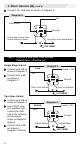
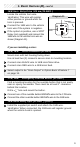
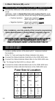
Two-Stage Unlock
Connect the 2/B wire as shown in Diagram 8 (page 6).
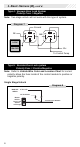
Connect the 24/B wire as shown in Diagram 9 (below).
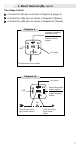
Connect the 14/B wire as shown in Diagram 10 (below).
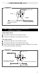
1. Basic Harness (B),
cont’d.
86
87
85
30
87a
Ground for negative
polarity system
+12v fused for
positive polarity
system
+12v fused
To vehicle door lock module
24/B
Diagram 9
86
87
85
30
87a
X
From Driver’s Door
Only Unlock Switch
14/B
+12v fused
Cut
To Driver’s Door
Only Unlock
Motor
Diagram 10
Ground for positive
polarity system
+12v fused for
negative polarity
system