
Installation Manual

6
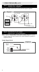
Diagram 7
2B
Ground
14B
12v
To Control Pump
LOCK
UNLOCK
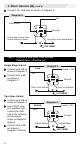
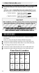
Type 5: Resistor Door Lock system
Polarity Fuse = Positive/Negative
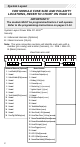
Note: Refer to Vehicle Wire Color and Location Chart for correct
polarity. Move the fuse inside of the control module to positive or
negative polarity.
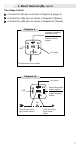
Single Stage Unlock
Diagram 8
MODULE
WIRES
TO DOOR LOCK MODULE
2 / B Lock
14 / B Unlock
Master
Vehicle
Door Lock
Switch
or Plunger
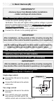
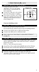
1. Basic Harness (B),
cont’d.
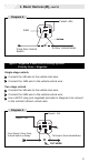
Type 4: Vacuum Door Lock System
Polarity Fuse = Negative
Note: Two-stage unlock will not work with this type of system.