
Installation Manual

2
System Layout
System Layout Power Elite PC 4100
TM
Security
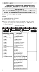
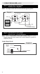
A = Advanced Harness (Optional)
B = Basic Harness (24 pin)
Note: The wire connection sections will identify each wire with a
number (pin cavity) and a letter (harness), i.e.: 20/B = Wire 20,
B (Basic) Harness.
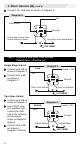
View from wire end:
123 4
PATS/VATS HARNESS
12345
EXTENDED RANGE HARNESS
Advanced Harness (Optional) Basic Harness
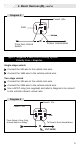
1. Lock Switch (87a) (BLUE/BLK) 1. Parking Light Output (WHITE)
2. Unused 2. Lock Motor Output (BLUE)
3. Unlock Switch (87a) (GRN/BLK) 3. Unused
4. Unused 4. Battery (+12v) (RED)
5. Unused 5. Ground (BLACK)
6. Unused 6. Starter Key (+) (VIOLET/RED)
7. Unused 7. Ignition 1 Input` (+) (PINK)
8. Unused 8. Starter Motor (+) (VIOLET)
9. Trunk Switch (87a) (TAN/RED) 9. Unused
10. Unused 10. Multiplex Output (YL/WHT)
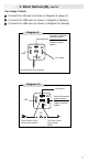
11. Unused 11. Unused
12. Unused 12. Unused
13. Unused 13. Tr unk Motor Output (TAN)
14. Unused 14. Unlock Motor (GREEN)
15. Unused 15. Siren Feed (+12v) (PLUG-IN)
16. Door Trig 10k Pull-up (RED) 16. Horn/Siren Drive (-) 1 Amp (PLUG-IN)
17. Disarm/Override Button (Ground) (PLUG-IN)
18. Disarm/Override Button Input (PLUG-IN)
19. Hood Pin Input (-) (GRAY)
20. Door Trigger (GRN/VT)
21. Unused
22. LED 2 (Red) (PLUG-IN)
23. LED 1 (Black) (PLUG-IN)
24. Second Door Unlock (-) 500ma (BLU/GRN)
01112131 415161314151617181 91021222324278 901
123456789123456789 011121123456
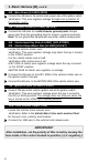
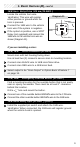
IMPORTANT!!!
The module MUST be programmed before it will operate.
Refer to the programming instructions on pages 11-13.
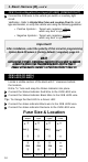
FOR MODULE FUSE SIZE AND POLARITY
LOCATIONS, REFER TO CHART ON PAGE 10.