
User's Manual
MAY/23/ 2003
RST771IN
2
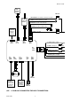
INSTALLATION
DIAGRAM …………….……………………………………………….…………………………. …4
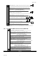
H1: 6 PIN HEAVY GAUGE WIRING
CONNECTION …………………………….………………..…….……. …6
H1/1 Violet Wire – Starter Output ………………….…………………………….……………………….……... 6
H1/2 & H1/3 Red Wire – +12V Power Input ………………………………….…………………...……………. 6
H1/4 Yellow Wire – Ignition 1 Output ……………………….…………………….……..…….…..…….……….
6
H1/5 Pin Wire – Ignition 2 Output ……………………………….…………….……..…….…..…….…………...
6
H1/6 Brown Wire – Accessory Output (Heater /ACC Output) ………………….……..……...….…………….
6
H2: 5 PIN WIRE HARNESS …..………………………………………………………….………………..………….
7
H2/1 Red / White wire – Parking Light Relay Power Input ……………………….……..……...….….……….
7
H2/2 White wire – Parking Light Relay Output ………………………………….……..………….….………….
7
H2/3 Black wire – System Ground ……………………………………………….……..………………...………
7
H2/4 Brown wire
– Siren Drive Output ………..………………………………….……..…………..……………
7
H2/5 Red wire – System Power ………………….…………………………….………………..………………..
7
H3: BLACK 4-PIN CONNECTOR FOR TWO-WAY TRANSCEIVER/ANTENNA MODULE ……….…….…...
7
H4: 3-PIN BROWN CONNECTOR FOR OPTIONAL PAGING (KNOCK) SENSOR ……………………....…..
7
H5: 8 PIN MINI BLACK INPUT WIRE CONNECTOR …..………………………………………………….……...
7
H5/1 White / Black wire – Negative Safety Shut Down Input (Hood -) .……….………………….….…..……
7
H5/2 White / Violet wire – Positive Safety Shut Down Input (Brake +) .……………….………………..…… 8
H5/3 Black / White wire – (-) Remote Start Enable Toggle Switch Input …….………………………..……...
8
– (-) Neutral Safety Switch Input ………………….…………………………….……..
8
H5/4 Blue wire – Ground Instant Trigger Input (Zone 2) .……………………….………………...……….…...
8
H5/5 Green wire
– Negative Door Switch Sensing Input (Zone 3) .………….………………..…….….……..
8
H5/6 Violet Wire – Positive Door Switch Sensing Input (Zone 3) .………….………………..………...……...
8
H5/7 White / Blue wire – (-) Instant Start & Turn Off Input ………………….……………………….…..….….
8
H5/8 White / Red wire – Tachometer Signal Connection ……….……………………..……….………………
8
H7. 4 PIN ORANGE CONNECTOR FOR 2 STAGE SHOCK SENSOR (ZONE 1 / 4) ….…………….…..……
9
H8: 10-PIN MINI WHITE OUTPUT WIRE CONNECTOR ……………………………………………….…..….… 9
H8/1 Yellow wire
– (-) 200mA Ignition 3 Output .………………………….………………..……..….….……
9
Transponder Interfacing
GM VATS Key Override
H8/2 Black / Violet wire – (-) 200mA Timer Control Channel 6 Output ……….…………………..…………
10
H8/3 Brown / White wire – (-) 200mA Programmable Output ……………….……………...….…..…...……
10
Horn Output – (Factory Default Setting)
Factory Security Rearm Signal Output
H8/4 White wire – (-) 200mA Dome Light Control Output ……………….………………..……….…....……
10