MAY/23/ 2003 MODEL RST771 REMOTE ENGINE STARTER WITH ALARM SYSTEM INSTALLATION MANUAL TABLE OF CONTENTS: RST771IN 1
MAY/23/ 2003 INSTALLATION DIAGRAM …………….……………………………………………….…………………………. …4 H1: 6 PIN HEAVY GAUGE WIRING CONNECTION …………………………….………………..…….……. …6 H1/1 Violet Wire – Starter Output ………………….…………………………….……………………….……... 6 H1/2 & H1/3 Red Wire – +12V Power Input ………………………………….…………………...……………. 6 H1/4 Yellow Wire – Ignition 1 Output ……………………….…………………….……..…….…..…….………. 6 H1/5 Pin Wire – Ignition 2 Output ……………………………….…………….……..…….…..…….…………... 6 H1/6 Brown Wire – Accessory Output (Heater /ACC Output) ………………….……..…….
MAY/23/ 2003 H8/5 Black / Red wire – (-) 200mA Timer Control Channel 5 Output ……….………………….…..….…… 10 H8/6 Black / Green wire – (-) 200mA Programmable Output …………….….…………….…..………..…… 10 Programmable Timer Channel 4 Output – (Factory Default Setting) Key Sensor By-Pass Output H8/7 Gray wire – (-) 200mA Channel 3 Output ….…………………………….…………..…………….….. 11 H8/8 Pink wire – (-) 200mA Programmable Output …………………………….……………….…………….
MAY/23/ 2003 Tachometer Checking Type – RPM Learning & Testing …………………………………………………. 19 Voltage Checking Type – Start Timer Set-up & Testing ……………………….…………………………. 19 Timer Checking Type – Start Timer Set-up & Testing …………….…………….…………………….….. 20 Test Mode ………………………………………………………………………………………..………..…... 20 RETURN TO FACTORY DEFAULT SETTING ………………………………………..……………..…….…….. 21 SHUTDOWN DIAGNOSTICS ………………………………………..……………………….……….………..…... 21 TESTING YOUR INSTALLATION ………………………………………..……………..……………………..…...
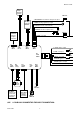
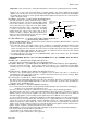
MAY/23/ 2003 Optional Pager (Knock) Sensor 15A Fuse 1. Red / White: Turn Indicator Relay Power input Two Way Transceiver Antenna 2. White: Parking Light Relay Output 3. Black: Ground to Vehicle Frame 4. Brown: Positive Output to Siren 3A Fuse H5 8 Pin Black Connector For Input Connection 5. Red: +12V Input H2 5 Pin White H3 4 Pin Black H4 3 Pin Brown H5 8 Pin Black 1. Violet: Starter Output 2. Red: +12V Input H1 6 Pin White 3. Red: +12V Input 20A Fuse 20A Fuse 4. Yellow: Ignition 1 output 5.
MAY/23/ 2003 1. White / Black Wire: (- ) Negative Safety Shut Down Input for Hood pin switch 2. White / Violet Wire: (+ ) Positive Safety Shut Down Input for Brake switch. 3. Black/White Wire: ( -) Neutral Safety Switch Input & ( -) Remote Start Toggle Switch Input 4. Blue Wire: Zone 2 / Instant Trigger Ground 5. White / Blue Wire: ( - ) Instant Start and Turn Off Input 6. Green Wire: Zone 3 / Negative Door Pin Trigger Input: +12V 7. Violet Wire: Zone 3 / Positive Door Pin Trigger +12V 8.
MAY/23/ 2003 Keep wiring away from moving engine parts, exhaust pipes and high-tension cable. Tape wires that pass through holes on the firewall to prevent fraying. Watches out sharp edges that may damage wires and causes short circuit. CAUTION: Do not connect the wire harness to the control module until all wiring to vehicle is complete.
MAY/23/ 2003 H2: 5 PIN WIRE HARNESS: H2/1 Red / White wire – Parking Light Relay Power Input – The RED/WHITE wire is the input to the flashing parking light relay. The connection of the RED/WHITE wire will determine the output polarity of the flashing parking light relay. If the vehicle you are working on has +12volt switched parking light, you don’t need connect this wire. This wire already connected to +12 volt.
MAY/23/ 2003 Important! This connection is a safety wire and must be connected as shown and tested as specifiled. Failure to do so may result in personal injury or property damage. See detail of wiring in the following diagram. This wire may also be used if the vehicle brake light circuit switches ground to the brake lights. An isolation diode must be used for ground switched brake light circuits and must be connected to the output of the brake switch.
MAY/23/ 2003 3. Start and run the vehicle. 4. Probe the wire you suspect of being the tachometer wire with the red probe of the meter. 5. If this is the correct wire the meter will read between 1V and 6V. H7. 4 PIN ORANGE CONNECTOR FOR 2 STAGE SHOCK SENSOR (ZONE 1 / 4) 1. Green Wire / Zone 1 Warn Away Input 2. Blue Wire / Zone 4 Ground Trigger 3. Black Wire / Negative 4.
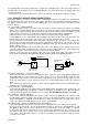
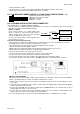
MAY/23/ 2003 Matching Resistor 87 VAT wire (#1) YELLOW wire 87a 85 86 To + 12 V VAT wire (#2) 30 Ignition Switch VATS control Module H8/2. Black / Violet wire – (-) 200mA Timer Control Channel 6 Output – (See Alarm Feature III – 7 Programming) (Factory default setting on momentary grounded) This wire is built-in user-programmable timer output provides a ground through this wire. Press the transmitter and button at the same time.
MAY/23/ 2003 This output is for a Key sense wire by-pass that some Chrysler and Toyota vehicles need to activated remote start. It wire come on when the start is activated and stay on for 20 seconds. H8/7 Gray wire – (-) 200mA Channel 3 Output – This will become a 1 second pulse ground by activate channel 3 on transmitter for two seconds, the current capacity of this wire is 200 mA. This feature allows you to remote control trunk release or other electric device.
MAY/23/ 2003 housing. Once a suitable location is chosen, drill a 6mm hole. Run the LED wires through the hole then press the 2 pin LED housing into the place. Route the LED wires to the control module. H6.
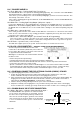
MAY/23/ 2003 2 STEP DOOR UNLOCK WIRE CONNECTION FOR 2 STEP DOOR UNLOCK WIRE CONNECTION FOR GROUND SWITCHED DOOR LOCKS POSITIVE SWITCHED DOOR LOCKS H8/8: 10-Pin Plug From Alarm +12V H8/8: 10-Pin Pink Wire Plug From Alarm OEM Door Master Lock Switch Pink Wire Unlock Lock Existing Neg. Unlock 86 87A Lock 85 Existing Pos. Unlock Wire 30 Existing Neg. Lock Wire Unlock Wire Green Wire Door Lock OEM Door Master Lock Switch 87 + 12V Existing Pos.
MAY/23/ 2003 button corresponding to the feature ‘Arming mode’ you want to 3 Press and release the transmitter program. [1] LED flash, [1] chirp to indicate you are in features “Active Arming”. 4 Depress the transmitter button twice to change the feature. [3] LED flash, [3] chirps to indicate your are in features “Passive Arming with Passive Door Locking ”. 5 Depress the transmitter program……..
MAY/23/ 2003 Ignition controlled door locks & unlocks Pathway illumination feature “off” 2 3 H2/5 Brown Wire = Constant Siren output 4 Ignition controlled door locks only Ignition controlled door unlocks only Parking light turns “on” for 30- second upon an unlock signal Parking light turns “on” for 30- second upon an unlock signal & 10-second upon a lock signal.
MAY/23/ 2003 7 + H8/2 Black / Violet Wire Channel 6 Output = Momentary output H8/2 Black / Violet Wire Channel 6 Output = Latched output H8/2 Black / Violet Wire Channel 6 Output = Latched output and reset with ignition “on” H8/2 Black / Violet Wire Channel 6 Output = Timer programming (set to any interval between 1 second and 2 minutes.) Exit: Turn Ignition to 'ON' position, or leave it for 15 seconds. A 3 long chirps & 3 parking light flashes to confirm exit.
MAY/23/ 2003 will report the new code three times with a one-second’s pause between each code. Note: If 15 seconds of inactivity expire, or if the ignition switch is turned “ON” for more then 5 seconds during of above steps, the unit will revert back to the last successfully stored code. A [3] long chirps to confirm exit.
MAY/23/ 2003 SAFE START (Child safety mode) Factory defaults setting to press the button twice to start the vehicle. Programming this feature to eliminate an accidental remote start, when kids enter this transmitter, it requires: 1. The user press the transmitter and buttons at the same time to start the vehicle. START FEATURE “II” PRORAMMING: 1. Turn the Ignition switch ‘ON/OFF’ 3 TIMES and stay in OFF position. 2.
MAY/23/ 2003 button twice on the transmitter to stop engine running. You have been completed this a. Press the programming successfully. b. Press button on the transmitter to exit the program mode. There will be 3 long chirps & 3 parking light flashes for confirmation. 3. If the crank time is too short, (Engine not running, while stops cranks): a. Press the button on the transmitter to stop engine running. Press button on the transmitter to set proper “Check Level ” to Hi position.
MAY/23/ 2003 and button at the same time to set the “Timer Checking Type”. [3] LED flash, 3. Press the transmitter [3] chirp to confirm this setting 4. Once you complete step 3, you can adjust and test “Start Timer” as below: START TIMER PROGRAMMING: (TEST and ADJUST) While the system stay in Start Feature “II” programming mode, 1. Press the button twice on the transmitter to start the vehicle. 2. If everything goes well: a. Press the ' button twice on the transmitter to stop engine running.
MAY/23/ 2003 Exit: Turn Ignition to 'ON' position, or leave it for 15 seconds. A 3 long chirps & 3 parking light flashes to confirm exit. SHUTDOWN DIAGNOSTICS The unit has the ability to report the cause of the last shutdown of the remote start system. Enter: 1. Turn the Ignition 'switch to ‘ON position. 2. Press the button on the transmitter. 3.
MAY/23/ 2003 Starts Wiring to accommodate this vehicle. The information concerning the Mechanical Neutral Safety Switch provided below will help you to determine if the vehicle you are working on has this type of safety switch and will provide alternate wiring methods to accommodate this situation. MECHANICAL NEUTRAL SAFETY SWITCH CONSIDERATIONS: Mechanical neutral safety switch configurations differ slightly in that they do not offer the same level of safety when installing a remote start device.
MAY/23/ 2003 METHOD 1 Drivers Door Pin Switch 85 Key In Chime Module 87 30 Ignition Key In Sensor Switch Closes with Key In Ignition Cylinder 87a Connected to (-) Negative Safety Input Wire White/ Black (H5/1) + 12V + 12 V 86 1N4003 To Hood Pin Switch Safety Shut Down (H5/1) To connect to the key in sensor as shown in method 1: A. Locate the control wire that connects the drivers door pin switch to the key in sensor switch. B.