
User's Manual


OCT/02/2002
CA-120
4
87
87a
85
30
86
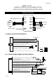
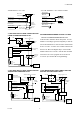
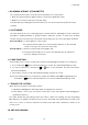
IN4003 Diode
H7/5
: ORANGE wire
from control module
“Start”
“On”
White wire
X
Cut
Red wire
Orange wire
“Acc”
“Off”
Starter
Yellow wire to
Ignition Switch
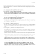
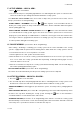
H7/6 . Gray wire – (-) 200mA Programmable Output –
CHANNEL 3 OUTPUT (Factory default setting)
This will become a 1 second pulse ground by press and hold the
button on transmitter for two
seconds, the current capacity of this wire is 200 mA. this feature allows you to remote control trunk
release or other electric device.
2 STEPS UNLOCK OUTPUT (Set Feature
III – 2
Programming to “2 Step Door Unlock Output)
The 2 steps unlock feature will work for the most fully electronic door lock circuit. The vehicle must have
an electronic door lock switch (not the lock knob or key switch), which locks and unlocks all of vehicle's
doors. When wired for this feature, press the
button one time will disarm the alarm and unlock the
driver's door only. If, press button two times within 3 seconds, the alarm will disarm and all doors
will unlock.
PAGER OUTPUT (Set Feature
III – 2
Programming to “PAGER Output)
This wire provides a negative output, when the alarm triggered. The current capacity of this wire is
200mA. For optional electrical device in this system, please connected to an additional relay. (I.E. Pager
interface....)
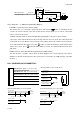
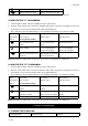
H4: 6 PIN DOOR LOCK CONNECTOR :
Blue/White
Wire:
(30
) - Door Unlock Relay
Blue/Red
Wire:
(87a)
- Door Unlock Relay
Blue/Yellow
Wire:
(87)
- Door Unlock Relay
Green/Red
Wire:
(87a)
- Door Lock Relay
Green/White
Wire:
(30
) - Door Lock Relay
Green/Yellow
Wire:
(87)
- Door Lock Relay
INSTALL NEW DOOR LOCK MOTORS
+12V
Green/ white
Blue/ white
Blue/ red
Green/ red
Green/ yellow
Blue/ yellow
NEGATIVE TRIGGER DOOR LOCK SYSTEM
Blue / white
Green / white
Door Lock
Master
Locking
Switch
Door unlock
Green /
y
ellow
Blue / yellow
POSITIVE TRIGGER DOOR LOCK SYSTEM
Blue / white
Green / white
Door Lock
Master
Locking
Switch
Door unlock
Green /
y
ellow
Blue / yellow
+ 12V
+ 12V