
User's Manual

OCT/02/2002
CA-120
3
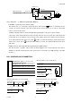
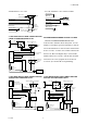
Route the red, black, blue and green wires in the 4 pin white connector from shock sensor to the control
module, and plug one end into the shock sensor, and the other end into the mating orange connector on the
side of the module.
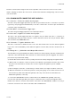
H7: 6-PIN MINI WHITE CONNECTOR WIRE HARNESS :.
H7/1. Violet wire – Positive Door Switch Sensing Input –
This wire is the positive trigger input wire for positive door pin switch. This wire is connection for "positive"
type factory door pins(typical FORD MOTOR). Locate the "common wire" for all door pins and make the
connection of the Violet Wire here.
H7/2. Blue WIRE -- Ground Instant Trigger Input –
This wire is the ground trigger input wire for hood/trunk pin switches.
H7/3. Green wire – Negative Door Switch Sensing Input –
This wire is the ground trigger input wire for negative door pin switch. This wire is connection for
"grounding" type factory door pins locate the "common wire" that connects the door pin switches. Make
the connection of the GREEN Wire here.
H7/4. Yellow wire – To Ignition Switched +12V –
This wire is connected to a switched 12 volts source. This wire should receive "12 volts" when the ignition
key is in the "ON" and "START" position. When the ignition is turned "OFF", this wire should receive "0"
voltage.
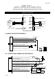
H7/5. Orange wire – (-) 200mA Grounded Output When Armed –
This wire will become grounded when the alarm is armed. The current capacity of this wire is 200mA. This
output can control starter disable, when an intrusion is detected and the system is triggered. The vehicles
prevent from any unauthorized starting.
a). Find the wire from the starter solenoid, (usually located on the starter) and going to the ignition switch.
b). When found, use voltmeter, connect one probe of the voltmeter to ground and connect the other end of
the probe to the starter wire, it should receive "12 volts" only when the ignition key in the "START"
position.
c). After locating the correct wire, cut it in half, try to start the vehicle. The engine should not "crank over".
d). When the extend wires are needed, they must be exactly same gauge as the cut wire. Connect the cut
wire from the key switch to the RED wire (pin #30) of the relay, and connect the starter wire to the
WHITE wire (pin #87a ) of the relay.
e). Connect the ORANGE Wire from the control module to the ORANGE wire (pin #86) of the relay.
f). Connect the Yellow wire (pin #85) of the relay to a switched 12 volts source from the ignition switch.
NOTE: If more than one electronic device will be connected to the ORANGE Wire, it will be necessary to
isolate the connection of each device control wires with a 1N4003 diode.