
User manual


2
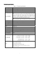
Cable connector pin-outs descriptions
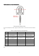
Cable connector interface pin-outs
The pin-outs descriptions in Table 1 apply to the cable connector on the scanner and are for reference
only.
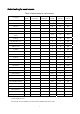
Table 1-2 Cable connector pin-outs descriptions
Pin RS232 Keyboard (PS2) USB
1 Power (+5V) Power (+5V) Power (+5V)
2
+3.3V ( for interface auto
selection purpose)
Ground (for interface auto
selection purpose)
+3.3V ( for interface auto
selection purpose)
3 Ground Ground Ground
4
+3.3V ( for interface auto
selection purpose)
Reserved
Ground (for interface auto
selection purpose)
5 TxD KeyClock Reserved
6 RxD KeyData Reserved
7 Reserved TermClock Reserved
8 Reserved TermData Reserved
9 RTS Reserved D+
10 CTS Reserved D-
Note: Voltage level of all RS232 Pin-outs (RxD, TxD, CTS and RTS) is 0V for logic low and 3.3V for logic
high.