Troubleshooting & Service for GL/GS Systems 50 Hz 1
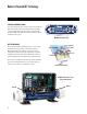
Balboa’s Patented M7 Technology TOPSIDE CONTROL PANEL Time The control panel activates functions at the touch of a button. Each function will echo from the circuit board to the LCD in a corresponding manner. The panel will also display diagnostic messages that enable the service technician to easily troubleshoot the system.
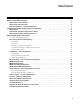
Table of Contents Balboa’s Patented M7 Technology . . . . . . . . . . . . . . . Balboa Service Tools Checklist. . . . . . . . . . . . . . . Balboa Service Parts Checklist . . . . . . . . . . . . . . . Important Information -- Product Identification . . . . . . Troubleshooting & Servicing Spa and Electrical Equipment Wiring Checks . . . . . . . . . . . . . . . . . . . . . . . . . 230 Volt 50 Hz - Residual Current Devices (RCD’s) . . . . Wiring Check for RCD and Service Disconnect. . . . . .
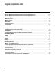
Diagrams (in alphabetical order) 230 Volt / 50 Hz Residential Wiring Schematic with 2 Pole RCD Breaker Box . . . . . . . . . . . . . . . . . . . . 10 230 Volt / 50 Hz Residential Wiring Schematic with 4 Pole RCD Breaker Box . . . . . . . . . . . . . . . . . . . . 12 500DZ Series Panel . . . . . . . . . . . . . . . . . . . . . . . . . . . . . . . . . . . . . . . . . . . . . . . . . . . . . . 36 500SZ Series Panel. . . . . . . . . . . . . . . . . . . . . . . . . . . . . . . . . . . . . . . . . . . . . . . .
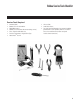
Balboa Service Tools Checklist Service Tools Required UÊ UÊ UÊ UÊ UÊ UÊ UÊ Ammeter (50A) Balboa Six-in-one Screwdriver Digital Multi-meter Padlock (to lock electrical disconnect during service) Pliers: Slip Joint & Needle nose Precision Thermometer - Digital Fever Type Quick CheckTM Test Kit UÊ Silicone Tube UÊ Small Wire Cutters UÊ Two 3/8” Open End Wrenches (one wrench should be ground down to 5/32” [0.
Balboa Service Parts Checklist Recommended Parts For Service Calls UÊ UÊ UÊ UÊ UÊ Extra Board(s) Extra Panel(s) Fuses Jumpers Heater Assembly COMMON FUSES USED 20618 JUMPER LOGIC 30074 30075 30122 30595 30076 30596 30142 30123 30137 21447 30136 FUSE 1 AMP FAST BLOW GLASS FUSE 5 AMP FAST BLOW GLASS FUSE 10A BLOWER FUSE 10A POWER INPUT FUSE 15 AMP FAST BLOW CERAMIC FUSE 15A POWER INPUT FUSE 20A POWER INPUT FUSE 20A PUMP FUSE 25A POWER INPUT FUSE 25A POWER INPUT HIGH SURGE FUSE 30A POWER INPUT Time War
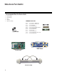
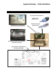
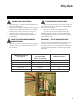
Important Information -- Product Identification Two Types of Plug-in Connectors: “Molex” Type, ML/GL Connector On Every System, an Identification Label Is Placed on top of the Casing “Phone Plug” RJ Type, VL/GS Connector Heater Element Specifications Are Shown on the Heater Tube Label On Every System, a Wiring Diagram Is Placed Inside the Door 7
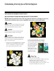
Troubleshooting & Servicing Spa and Electrical Equipment HIGH VOLTAGE CAN SERIOUSLY INJURE OR KILL! ONLY EXPERIENCED TECHNICIANS SHOULD SERVICE THIS EQUIPMENT. DO NOT remove the protective covers from any electrical enclosure, or attempt to service any related electrical device, unless you are a qualified electrician or service professional. DANGER Risk of electric shock. Before working with any electrical connections, make certain that the Main Power breaker from the house breaker box has been turned off.
Wiring Checks WIRING CHECK PRECAUTIONS SYSTEM BOX WIRE GAUGE CHECK UÊ When working in a system box always be aware that it may contain high voltage. UÊ Always keep your fingers and hand tools away from any wiring or circuit board when the power is on. Touching anything in these areas can result in serious injury. UÊ All service calls, no matter how minor, should include a complete wiring check, beginning with the house breaker.
230 Volt / 50 Hz Residential Wiring Schematic with 2 Pole RCD Breaker Box 9 OFF ON OFF ON OFF ON ON OFF OFF OFF OFF 8 OFF ON ON ON ON 12 RCD Breaker Box Neutral + Ground 230 VAC “Live Wire” 230VAC House Breaker Box 7 6 ON 11 OFF 10 Outside Ground Rod Correct Voltage 0v 207V - 253V 10 When Probes Are Placed Across [1 - 3] [4 - 7] [5 - 9] [10 - 11] [1 - 2] [2 - 3] [4 - 6] [5 - 8] [6 -7] [8 - 9] [10 - 12] [11 - 12]
Spa System Box AV J50 J23 J29 OZONE J51 F6, T30A 480V G N G N J47 K9 PUMP 1 G J32 N N CIRC. PUMP J25 G J52 TB1 T J58 BROWN W2 J28 K3 1 K4 BROWN SERVICE 2 BROWN LINE 1 2 J26 SERVICE 1 INPUT RATING 230V/32A 1 ERVICES (REMOVE JUMPER A) 5 BROWN LINE 2 INPUT RATING 230V/16A 2 ERVICES (REMOVE JUMPER A) 3 F4, T0.
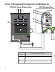
230 Volt / 50 Hz Residential Wiring Schematic with 4 Pole RCD Breaker Box RCD Breaker Box Neutral + Ground 230 VAC “Live Wire” 230VAC House Breaker Box 1 3 N N 4 N N OFF ON OFF ON OFF ON ON OFF OFF OFF 10 OFF OFF ON 19 11 ON 20 12 ON ON 13 2 18 ON 17 OFF 16 Outside Ground Rod Correct Voltage 0v 207V - 253V 12 When Probes Are Placed Across [1 - 5] [6 - 8] [7 - 14] [7 - 17] [16 - 17] [3 - 5] [6 - 9] [7 - 15] [7 - 18] [16 - 18] [2 - 5] [6 - 10] [7 - 12] [1
Spa System Box AV J50 G N G N J47 G G J32 N CIRC. PUMP J25 TB1 K3 J26 1 K4 BROWN SERVICE 2 2 J57 Balboa 6 AV J50 J52 J51 F6, T30A 480V J23 J29 OZONE G J100 HTR1 F1 F7 F10A 250V K1 K6 K9 PUMP 1 J101 HTR2 W1 BALBOA INSTRUMENTS, INC. GS500Z Pb COPYRIGHT 2007 MADE IN U.S.A. P/N 22015_B 4 3 W2 J28 BROWN LINE 1 INPUT RATING 230V/32A 1 ERVICES (REMOVE JUMPER A) 7 T J58 BROWN SERVICE 1 5 8 F4, T0.
230 Volt 50 Hz - Residual Current Devices (RCD’s) A residual current device (RCD, or R.C.D. henceforth) is the generic term for a device that monitors the current in the line conductor and the neutral conductor of a circuit in an earthed system. Two Pole RCD In a circuit that’s operating properly, the vector sum of the live and neutral current values added together will be zero.
Wiring Check for RCD and Service Disconnect RCD LINE-OUT WIRING CHECK FOR 230 V DEDICATED SYSTEM IMPORTANT! Remember, high voltage is still accessible in the house breaker box even though you have turned off the spa breaker. Keep in mind that a majority of R.C.D. tripping problems can be attributed to incorrect wiring. R.C.D. troubleshooting usually finds the problem.
Diagnosing M7 Topside Control Panels Panel messages are a quick clue toward solving a variety of problems. Here are the most common messages and what they mean. PRELIMINARY PANEL CHECK PANEL DISPLAY MESSAGES UÊ If the problem is not obvious, look on the topside control panel for diagnostic messages. If no messages are seen, run through all spa functions and note any inconsistent operation. UÊ Most error messages are stored in the fault log.
NOTE: A common programming mistake is overlapping filter times that may cause the spa to filter continuously. UÊ Check the water level. UÊ Check the water temperature with an accurate thermometer. Remove the spa cover and allow the water to cool to below 42°C. Adding cool water may be necessary. Touch any button to reset the system. If the water is still hotter than the set temperature, press the blower button (if applicable) to cool the spa.
Diagnosing M7 Topside Control Panels (cont.) SOME TROUBLESHOOTING SCENARIOS , or This indicates a persistent flow problem. The heater is shut down while all other spa functions continue to run normally. Power on the spa must be cycled before the heater will function again. THE PANEL DISPLAYS: , , or This indicates that there is not enough water in the heater. Spa shuts down for 15 minutes. This could indicate poor flow or air bubbles in the heater.
Basic Control System Troubleshooting LOW VOLTAGE CHECKING THE SYSTEM POWER INPUT FUSE At Balboa, it’s been our experience that the majority of the problems associated with electronic control systems are due to low voltage. Warning These procedures are performed while the system is powered up and running under peak loads. Be careful. BROWN OUTS “Brown outs” can have an effect on the spa’s operation in a variety of ways.
Basic Control System Troubleshooting (cont.) Once the power input fuse has been changed Test the Blower UÊ Check the voltage between the black and red wires again. Acceptable voltage range is between 216V and 264V. UÊ UÊ UÊ UÊ These readings should be taken under peak load conditions. Important If the voltage is not in the acceptable range, call an electrician or the local electric company to diagnose the problem.
Spa Behavior -- Start-up Information See manufacturer’s owners manual or reference card for general information on operating the spa, including programming filters and other settings that are changed from the topside control panel. PRIMING MODE HEATER START UP INFORMATION In Priming Mode, the “Mode” button toggles the ozone on/off (with a 15-second time-out). This can be useful if you want to verify ozone generator operation without waiting for a filter cycle.
ML Series Panels -- For Use with EL and GL Systems ML900 Time Warm Jets 1 Jets 2 Jets 3 Option Mode/Prog Cool Invert Fiber Light Blower F1 F2 PL TL ML700 Time Warm Light Blower Mode/Prog Cool Jets 1 Jets 2 F1 F2 PL TL ML553 ML554 “Molex” type ML/GL Connector Light Light Warm Warm ML551 Mode Heat Cool Blower Jets 2 Heat Cool Heat Jets Aux Temp ML200 ML240 ML260 ML400 ML550 Jets 1 22 Jets Jets Jets Aux Aux Temp Aux Temp Light Light Temp Light Light Warm
ML900 Panel Operation Diagnostic Messages section for the ML900 is unique. Refer to the User Guide for additional information. User Guide for panel ML900 is 40568-99. Initial Start-up Locking the Panel When your spa is first actuated, it will go into Priming mode (after displaying some configuration information). Please see “Spa Behavior -- Start-up Information” for additional information. Press “Time” “Jets 1” then “Warm” within 3 seconds. When locked, the PL “ PL ” light will light.
ML700 Panel Operation Diagnostic Messages section for the ML700 is unique. Refer to the User Guide for additional information. User Guide for panel ML700 is 40520-99. Initial Start-up Locking the Panel When your spa is first actuated, it will go into Priming mode (after displaying some configuration information). Please see “Spa Behavior -- Start-up Information” for additional information. Press “Time” “Jets 1” then “Warm” within 3 seconds. When locked, the PL “ PL ” light will light.
ML550, 551, 554 Panel Operation Please refer to the following User Guides for more detailed information: ML551/ML554 User Guide: P/N 40632-99 ML 550 User Guide: P/N 40569-99 Light Mode Warm Light Warm Mode Heat Heat Jets 1 Jets 1 Jets 2 Blower Jets 2 Cool Blower Cool ML551 ML554 Heat Cool Warm Jets 1 Jets 2 Blower Light Mode ML550 Cool/Warm ML500, 551, 554 Press the “Cool” or “Warm” button once to display the set temperature.
ML550, 551, 554 Panel Operation (cont.) Blower 1-speed operation: on/off; 2-speed operation: med/hi/off; or 3-speed operation: lo/med/hi/off. If left on, the blower will automatically turn off after a timeout period. NOTE: If your system does not have a “Blower” button, and is labeled as ”Jets 3” instead, please refer to the respective User Guide listed above. Light Some systems are equipped with both a spa light and a fiber optic light; however, only one can be accessed by this panel.
Clean-up Cycle (optional) When a pump or blower is turned on by a button press, a clean-up cycle begins 30 minutes after the pump or blower is turned off or times out. The pump and the ozone generator will run for one to four hours, depending on the system (on some systems, you can change this setting.) software version number (such as 2.1), followed by “ ” and then your spa’s network ID number (consisting of both letters and digits displayed in 5 steps).
ML550, 551, 554 Panel Operation (cont.) – Dolphin II Address When set to “ ”, no addressing is used. Use this setting for a Dolphin I, or for a Dolphin II which is set for no address (which is the Dolphin II factory default). When set to “ ” through “ ”, the number is the address (see your Dolphin II manual for details). Editing User Preferences View the setting.
ML200, 240, 260, 400 Panel Operation Please refer to the following User Guides for more detailed information: ML400 User Guide: P/N 40570-99; ML260 User Guide: P/N 40633-99 ML240 User Guide: P/N 40634-99; ML200 User Guide: P/N 40571-99 Heat Jets Jets Aux Temp Aux Temp Light Light ML400 ML 400 INTRODUCTION The pump responsible for heating and filtration (pump 1 low on non-circ systems, or the circ pump on circ systems) will be referred to simply as the pump.
ML200, 240, 260, 400 Panel Operation (cont.) Pressing “Jets” while in Economy mode puts the spa in Standard-In-Economy mode, (“ ”) which operates the same as Standard Mode, then reverts to Economy Mode automatically after 1 hour. During this time, pressing “Temp” followed by “Light” will revert the mode to Economy immediately. Sleep mode heats the spa to within 11°C (20°F) of the set ” will appear on temperature only during filter cycles. “ the display until mode is changed.
Ozone (optional) ML400 Preset Filter Cycles ML400 On most systems, the ozone generator (if installed) runs during filter cycles (except when pump 1 is operating at high speed on a non-circ system) and during clean-up cycles. On some systems, the ozone generator operates whenever the pump runs. If your system is configured with the optional ozone suppress feature, the ozone generator will turn off for 1 hour any time a function button (Jets, Jets 2, Blower, etc.) is pressed.
ML200, 240, 260, 400 Panel Operation (cont.) User Preferences ML400 Editing User Preferences ML400 There are several aspects of spa operation that you can customize using the User Preferences submenu. Press “Temp” then “Jets”, then “Light”. (Each press must be within 3 seconds of the previous press.) At this point, if “ ” is not showing on the display, press “Temp” until you see ” on the display. Then press “Jets” to enter the User “ Preferences submenu.
GL Series Mach 3 -- Persistent Memory & Power Up This document applies when using ML Series panels with any EL or GL Mach 3 series system.
VL Series Panels -- For use with GS Systems Warm Blower Light Mode / Prog Cool Jets 1 Jets 2 Time Warm Blower Light Mode/Prog Cool Jets 1 Jets 2 Mode Warm VL702S Blower Heat Jets 1 VL701S Blower Jets 2 Light Mode Cool Warm Heat Jets 2 Light Cool VL600S VL700S Jets 1 34 DELUXE SYSTEMS Time Jets Warm Mode Blower Light Jets Blower Light Heat Cool STANDARD SYSTEMS VL801D VL802D VL Panel Line-up “Phone Plug” RJ Type, VL/GS Connector
VL406U VL406T Jets Warm Light Cool Heat Jets Temp Blower Light “Phone Plug” RJ Type, VL/GS Connector Heat Set Heat VL403 Jets Light Note: VL404 and VL403 have red LED’s on black background Heat Blower Jets Temp Light VL402 Blower Heat Jets Heat Blower Jets Temp Light Set VL200 VL240 VL260 VL400 VL401 Light DUPLEX SYSTEMS VL404 Blower Blower Jets Blower Jets Temp Light Temp Light 35
GS Panel -- 500 Series and Operation Please refer to the User Guides for additional information. 500 Z Series User Guide: P/N 40789 500 SZ Series User Guide: P/N 40790 500 DZ Series User Guide: P/N 40788 Temp Te mpp J ts Je Blow Bl ower er 500Z Series Panel Warm Cool Mode Warm Cool Mode/Prog Time Initial Start-up Your spa will enter Priming Mode ( ) when it is energized. During Priming Mode, press “Jets” button(s) repeatedly and be sure all pumps are free of air.
On panels with “Warm” and “Cool” buttons, to display the set temperature, press “Warm” or “Cool” once. To change the set temperature, press a temperature button again before the display stops flashing. Each press of “Warm” or “Cool” will adjust the set temperature. After three seconds, the display will stop flashing and begin to display the current spa temperature. JETS Jets 1 500Z, 500DZ, 500SZ Series Press “Jets 1” to turn pump 1 on or off, and to shift between low and high speeds (if equipped).
GS Panel -- 500 Series and Operation (cont.) FILTER CYCLES Preset Filter Cycles 500Z UÊ The first preset filter cycle begins 6 minutes after the spa is energized. The second preset filter cycle begins 12 hours later. Filter duration is programmable for 2, 4, 6, or 8 hours or for continuous filtration (indicated by ). The default filter time is 2 hours. UÊ To program, press “Temp”, then “Jets 1”. Press “Temp” to adjust. Press “Jets 1” to exit programming.
GS Persistent Memory with VL Panels Power Up Display Sequence Any time you change a DIP Switch, other than A1, you must reset Persistent Memory for your new DIP Switch Settings changes to take effect. If you do not reset Persistent Memory, your system may function improperly. Upon power up, you should see the following on the display: > Three numbers in a row, which are the SSID (the System Software ID).
Changing a System Circuit Board HOW TO REPLACE A SYSTEM CIRCUIT BOARD Important! Be sure to turn the power off before replacing any component, especially a circuit board. Important! DO NOT REMOVE AND REPLACE THE CIRCUIT BOARD UNLESS THE FAULT HAS POSITIVELY BEEN DETERMINED TO BE THE CIRCUIT BOARD. HOW TO REMOVE A SYSTEM CIRCUIT BOARD NOTE: Before you begin, labeling all wires to be removed may help speed up reinstallation. The wiring diagram should always be used to ensure proper wire placement.
Testing the Sensor Set 1. UÊ If the opposite sensor is now reading higher, the problem is with the sensor(s). Replace the sensor set. *If you wait more than 2 minutes after plugging the sensors back in, heating may start (even outside a filter in Economy or Sleep mode) due to a stray Cd/CLd/COLD WATER condition usually detected when sensors are being plugged in while the system is running. Check sensor wires for cracks or damage that may indicate the presence of a rodent. 2.
Removing the Heater Assembly from a Spa System Note: Be careful when removing a heater assembly from a spa plumbing system. Water may splash out under pressure. Water under pressure in the plumbing may splash out, and onto the system’s electronic board. Do not remove the system door until the water has been drained from the heater assembly tube. 1. Turn off the main power. 2. Close off the slice valves (or, ball valves) adjacent to the heater assembly. 3.
Panel Message Reference Guide Message Meaning / Frequency Action Required 5FNQFSBUVSF OPU DVSSFOU JO &DPOPNZ PS 4MFFQ NPEF *O &DPOPNZ PS 4MFFQ NPEF UIF QVNQ NBZ CF PGG GPS IPVST PVUTJEF B mMUFS DZDMF *G ZPV XJTI UP TFF UIF DVSSFOU TQB UFNQFSBUVSF FJUIFS TXJUDI UP 4UBOEBSE NPEF PS UVSO +FUT PO GPS NJOVUFT 1MFBTF TFF i%JBHOPTJOH 5PQTJEF $POUSPM 1BOFMTw 1BHF $POmHVSBUJPO FSSPS 4QB DBOOPU TUBSU VQ 1MFBTF TFF i%JBHOPTJOH 5PQTJEF $POUSPM 1BOFMTw 1BHF "T OFFEFE < > *OTUBMM OFX
Panel Message Reference Guide (cont.) 5IF QVNQ JT PO EVSJOH 4UBOECZ .PEF UP BTTJTU JO ESBJOJOH UIF TQB 1SFTT i+FUT w UP UVSO PGG UIF QVNQ XIFO XBUFS IBT ESBJOFE PS QPXFS PGG UIF TQB *OBEFRVBUF XBUFS EFUFDUFE JO IFBUFS %JTQMBZT PO UIJSE PDDVSSFODF PG iESw NFTTBHF 4QB JT TIVU EPXO < > 'PMMPX BDUJPO SFRVJSFE GPS NFTTBHF 4QB XJMM OPU BVUPNBUJDBMMZ SFTFU 1SFTT BOZ CVUUPO UP SFTFU NBOVBMMZ 5IF TQB JT PQFSBUJOH JO &DPOPNZ .
i*DFw 1PUFOUJBM GSFF[F DPOEJUJPO EFUFDUFE /P BDUJPO SFRVJSFE 5IF QVNQT BOE UIF CMPXFS XJMM BVUPNBUJDBMMZ BDUJWBUF SFHBSEMFTT PG TQB TUBUVT 1FSTJTUFOU MPX nPX QSPCMFNT %JTQMBZT PO UIF mGUI PDDVSSFODF PG UIF i)FBUFS 'MPX -PXw NFTTBHF XJUIJO IPVST )FBUFS JT TIVU EPXO CVU PUIFS TQB GVODUJPOT DPOUJOVF UP SVO OPSNBMMZ 'PMMPX BDUJPO SFRVJSFE GPS i)'-w PS i)-w NFTTBHF )FBUJOH DBQBDJUZ PG UIF TQB XJMM OPU SFTFU BVUPNBUJDBMMZ ZPV NBZ QSFTT BOZ CVUUPO UP SFTFU &WFSZ EBZT < > *OTUBMM
Panel Message Reference Guide (cont.) [1] &WFSZ EBZT < > $MFBO DPOEJUJPO DPWFS QFS NBOVGBDUVSFS T JOTUSVDUJPOT Reminder, Suppress in User Preferences. [2] &WFSZ EBZT < > %SBJO BOE SFmMM TQB QFS NBOVGBDUVSFS T JOTUSVDUJPOT Reminder, Suppress in User Preferences. [2] &WFSZ EBZT < > 5FTU BOE BEKVTU Q) DIFNJDBM MFWFMT QFS NBOVG JOTUSVDUJPOT Reminder, Suppress in User Preferences.
4QB JT TIVU EPXO < > 5IF TFOTPS UIBU JT QMVHHFE JOUP UIF 4FOTPS i#w KBDL JT OPU XPSLJOH 5FTU TFOTPS BOE SFQMBDF JG CBE 1MFBTF TFF 5FTUJOH UIF 4FOTPS 4FU 1BHF 4FOTPST BSF PVU PG CBMBODF *G UIJT JT BMUFSOBUJOH XJUI UIF UFNQFSBUVSF JU NBZ KVTU CF B UFNQPSBSZ DPOEJUJPO *G UIF EJTQMBZ TIPXT POMZ UIJT NFTTBHF QFSJPEJDBMMZ CMJOLJOH UIF TQB JT TIVU EPXO < > 5FTU TFOTPS BOE SFQMBDF JG CBE 1MFBTF TFF 5FTUJOH UIF 4FOTPS 4FU 1BHF 4MFFQ .
©2008 Balboa Water Group. All rights reserved. Tustin, Ca.