
Owner`s manual
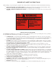

CS6230/CS6200 Control Equipment Pack System Wiring Directions
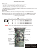
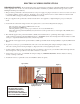
Remove 2 screws from cover panel
figure 1 and open carefully and set
aside.
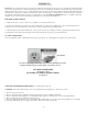
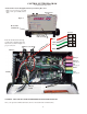
Route the electrical wires through
conduit of the equipment pack and
attach wires as shown in figure 2 to
proper connectors.
Red
White
Green
Black
Conector
Wirin
g
D
irections
Pressure
Switch
Fuses - SC-25
Figure 1
Figure 2
Panel Screws
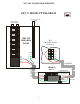
Pump 1
Pump 2
Air
Ozone
Aux
Heater Light
Indicator Light
CONTROL SYSTEM DIAGRAM
(see wiring diagrams pages 21-22)
Heater Tube
and Element
WARNING: FILL THE SPA WITH WATER BEFORE TURNING THE POWER ON.
Once your spa has been filled with water, turn it on and test all of the circuit breakers.
6
(If Equipped)
(If Equipped)
(If Equipped)
Conduit