
Owner`s manual

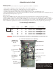

Model 510, as it comes from the factory is designed for 120 Volts, 20 Amp Circuit. The spa is also convertible to a 240 Volt, 40 Amp
System. The circuit must have a neutral wire and ground wire when converting the spa wiring to 240 Volts, 40 Amp using a minium
AWG 6/3 wires with ground (see page 3). The wiring must be connected to a grounded type G.F.C.I. (Ground fault circuit interrupter)
electrical service with copper conductor. This must be a separate circuit having no other appliances connected to the same circuit. To
determine the current and voltage and wire size required, refer to section POWER REQUIREMENTS page 3. A qualified electrician
should be used to ensure the necessary wiring and equipment for converting to this application.
ELECTRICAL PRECAUTIONS
1. Make sure the line cord does not lay across a walkway or in a heavily traveled area.
2. Do Not use electrically connected devices, such as a TV, radio or cooling devices within 5 fee of the spa when being used. If
electrical devices are used within 5 feet of the spa, they must be a G.F.C.I. Protected breaker/outlet.
3. All fixed metal objects located within 5 feet of the spa such as a fence post, railing, door frames, gutters must be attached to the
grounding bar by the outside of the electrical control pack, using #8 solid copper wire. (for Canada #6 wire).
120 VOLT CONNECTION
Your spa equipment requires a dedicated circuit 3-20 prong receptacle. No other appliances or lights can be on this circuit.
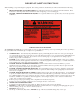
VOLTAGE CONVERSION INSTRUCTIONS ( see wiring diagram, page 21).
WARNING - Disconnect all electrical power to the equipment before attempting any conversion procedures.
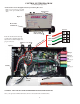
1. Remove door panel of the spa
2. Remove front panel of the equipment control box and locate the power terminal compartment.
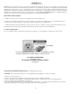
3. Remove and discard 120 Volt Power Cord with G.F.C.I. Plug. Never use 120 Volt power cord for 240 Volt application.
4. Remove Jumper L2-N on terminal block. (See Page 20)
5. Reconnect circuit board Jumper J1 to the left position (HC). With Jumper 1 to the left position heater will run on low and high
speed pump. With Jumper J1 to the right position heater will run on low speed pump only.
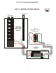
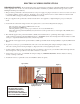
20 Amp Only
120 Volt System requires a three wire electrical service including the ground,
consisting of LINE 1 (Black), Neutral (White), and Ground (Green).
240 VOLT CONNECTION
(see pages 3, 5, 6)
ELECTRICAL WIRING INSTRUCTIONS
(see page 7)
MODEL 510
(see wiring diagram page 21)
4