
User manual

Code Mercenaries
1
MM
MM
WW
WW
22
22
44
44
JJ
JJ
88
88
--
--
MM
MM
OO
OO
DD
DD
1. Features
• Low Speed USB interface
• Full USB V1.1/2.0 compliance
• Full USB HID 1.1 compliance
• Uses 100K potentiometers for three axis
joystick or mouse with scroll function
• Up to 6 buttons supported
• On-the-fly switching between joystick and
mouse operation
• Autocalibration and autocentering
• Single +5V power supply
2. Functional overview
The MW24J8-MOD comes equipped with
MouseWarrior24J8 chips. It allows direct
connection of up to three 100k potentiometers and
up to 6 buttons.
The axes are used either for cursor control
emulating a six button mouse with scroll wheel or
as a three axis joystick. Switching between joystick
and mouse mode can be done at any time by
pulling the mode input low or high.
This allows to use one controller for the user
interface as well as for input into specialised
control software. By utilizing the USB standard
joystick protocol MW24J8 can be easily used via
the game controller input functions on any
operating system. At the same time the mouse
function can be used via the standard mouse driver
of the system.
The MW24J8-MOD has been optimized for the use
with 100k pots, any significant deviation (>±20%)
from this value results in reduced resolution of the
axis movement.
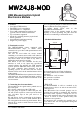
3. Connecting the electromechanics
The module has the signal names printed next to
the solder pads.
K1 is for the connection of the USB cable.
K2 is the group of signals to connect the pots. AZ,
AY, AX are the respective center taps for the three
pots. All three taps of the pots need to be
connected.
K3 and K4 are for the connection of the buttons.
The buttons have to close to GND. Buttons B0 to
B5 correspond to the mouse/joystick buttons. B6 is
unused, B7 is used to switch between mouse and
joystick mode.
JP1 is an optional jumper to enable the Raw mode
of the JoyWarrior for testing purposes.
For further details please refer to the
MouseWarrior24J8 datasheet.
Soldering wires to the module should be done
carefully to avoid separating the pads from the
PCB due to overheating or mechanical stress.
4. Mechanical dimensions
The mounting holes are 2.5mm in diameter.
The solder pad holes are 0.9mm in diameter.
Tolerances:
Hole diameters: -0.05 +0.1mm
Hole positions: ±0.05mm
Outer contour: ±0.2mm
5. FCC / CE
The MW24J8-MOD is sold as a module to be
integrated into a device. As such it can not be FCC
or CE approved.
Code Mercenaries has excerted greatest care in
designing this module to minimize RF emission
and assure stable operation. Though the use of
proper cable materials and correct integration into
a device is crucial to assure product safety and
interference free operation.
The integrator who assembles the module into a
device has to take care for appropriate testing and
safety measures.
32,2 mm
32,0 mm
37,0 mm
3,9 mm
28,0 mm
4,3 mm
GND
B1/X1
B3/X3
B5/Y1
B7/Y3
K3
K1
JP1
K4
GND
B0/X0
B2/X2
B4/Y0
B6/Y2
ZR2
AZ
ZR1
YR2
AY
YR1
XR2
AX
XR1
K2
V1.0.0 March 24th 2009
USB Mouse/Joystick Hybrid
Electronics Module